— Practical Reactive Power Compensation Explained by Kete Transformer
In modern power distribution systems, reactive power compensation plays a critical role in voltage stability, power factor correction, loss reduction, and the safe operation of transformers, box-type substations, and industrial loads.
Based on extensive experience in power transformers, distribution transformers, and box substations, Kete Transformer summarizes the practical roles and differences between SVG and SVC, two of the most widely used reactive power compensation solutions.
1. What Is SVG and What Does It Do?
SVG (Static Var Generator) is a typical power-electronic-based reactive power compensation device. It mainly consists of three functional modules:
- Detection module – collects current signals via external CTs
- Control & computation module – analyzes parameters such as PF, S, and Q
- Compensation output module – generates compensation current through an inverter
How SVG Works in Power Systems
The SVG control system continuously monitors grid current. Based on real-time analysis, the controller outputs a command signal to an inverter composed of self-commutated IGBT devices. The inverter then injects a precisely controlled compensation current into the grid.
Technical Principle of SVG
SVG uses a self-commutated bridge (voltage-source converter) connected to the grid through a reactor. By adjusting:
- the magnitude and phase of the AC-side output voltage, or
- directly controlling the AC-side current
the SVG can rapidly absorb or generate reactive power.
As an active compensation device, SVG offers:
- Fast dynamic VAR regulation
- Effective compensation for impact loads
- Capability to track and compensate harmonic currents
This makes SVG especially suitable for applications where transformers are exposed to frequent load fluctuations, such as steel plants, wind farms, and industrial substations.
2. SVG vs. SVC: Core Differences Explained
Terminology
- SVG = Static Var Generator
- SVC = Static Var Compensator
Both are used for reactive power compensation, but they differ significantly in technology, performance, and application focus.
(1) SVG – Active Reactive Power Compensation
SVG can provide:
- Lagging reactive power (inductive)
- Leading reactive power (capacitive)
By controlling the self-commutated bridge circuit via IGBTs, SVG directly generates the required reactive current. This allows:
- Extremely fast response
- Continuous and smooth VAR regulation
- Superior voltage control at transformer busbars
From a transformer application perspective, SVG is often selected to:
- Stabilize bus voltage
- Improve transformer power factor
- Reduce transformer current stress and losses
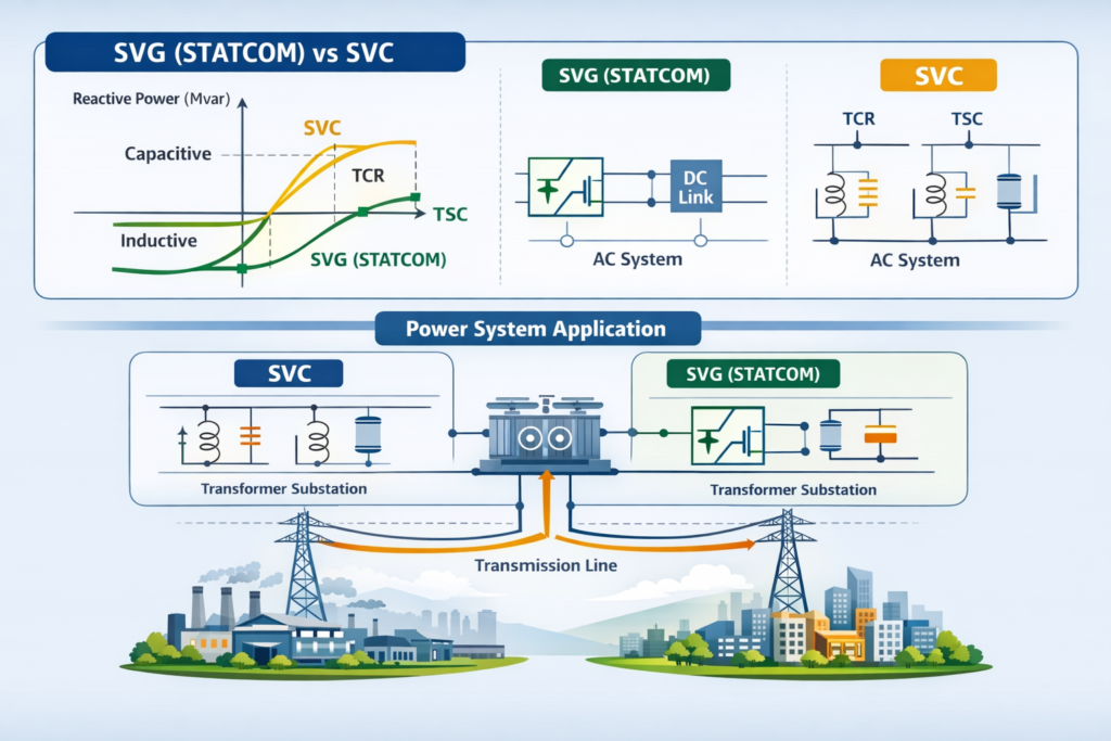
(2) SVC – Thyristor-Based Reactive Power Compensation
SVC is a classic and widely used reactive power compensation solution. It uses thyristors as solid-state switches to control the connection of:
- Reactors (inductive VAR)
- Capacitor banks (capacitive VAR)
By changing the equivalent system admittance, SVC provides reactive power support.
Common SVC configurations include:
- TCR (Thyristor Controlled Reactor)
- TSC (Thyristor Switched Capacitor)
- Hybrid reactor–capacitor combinations
SVC is commonly applied in substations and transmission systems where step or quasi-continuous reactive power regulation is sufficient.
3. Advantages of SVC
SVC systems offer several proven advantages:
- Digital control technology improves reliability and reduces maintenance cost.
- Excellent performance in improving transient stability and damping power system oscillations.
- Flexible control with fast response and wide regulation range in both inductive and capacitive modes.
- Fully static operation with no rotating machinery, resulting in low noise and long service life.
- Reduced demand for large capacitor banks and complex mechanical switching devices.
- Small connection reactance and mature engineering design.
4. SVG or SVC: How to Choose in Transformer Applications?
From Kete Transformer’s practical engineering perspective:
- Choose SVG when:
- Load changes rapidly
- Harmonic currents are present
- High power quality is required
- Transformer capacity needs to be utilized more efficiently
- Choose SVC when:
- Load variation is relatively slow
- Cost-effectiveness is a key factor
- The system is dominated by traditional inductive/capacitive loads
In many projects, SVG or SVC is installed together with power transformers or box-type substations to form an integrated solution that improves voltage quality, reduces losses, and extends transformer service life.
Conclusion
Both SVG and SVC play important roles in modern reactive power compensation systems.
When properly matched with transformers and substations, they significantly improve:
✔ Voltage stability
✔ Power factor
✔ Energy efficiency
✔ Equipment reliability
With deep experience in transformer manufacturing and power distribution solutions, Kete Transformer supports customers in selecting the most suitable reactive power compensation technology for each application scenario.