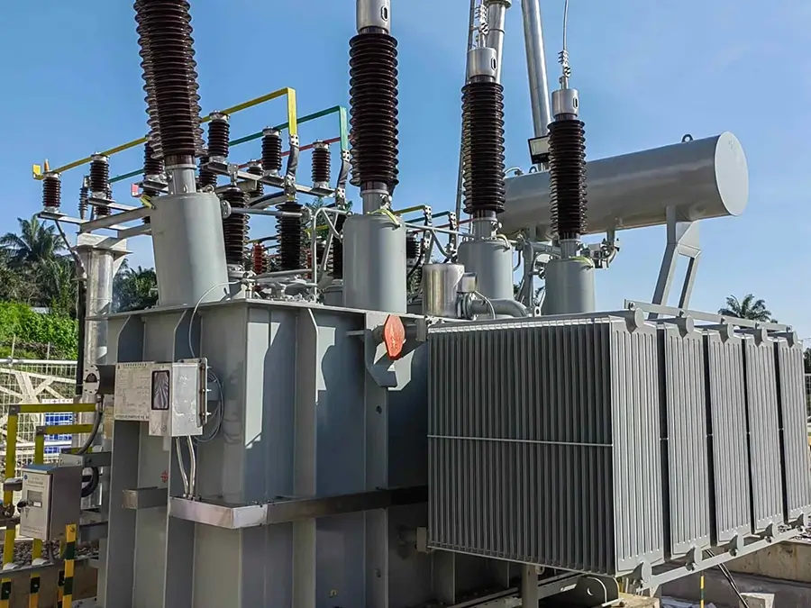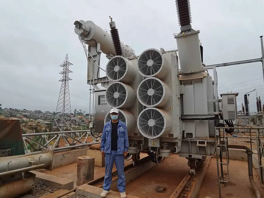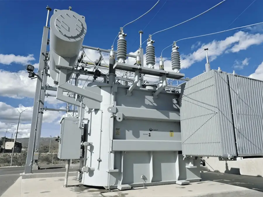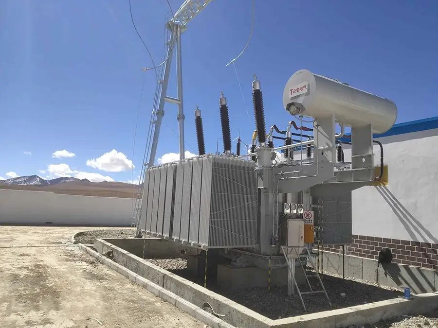




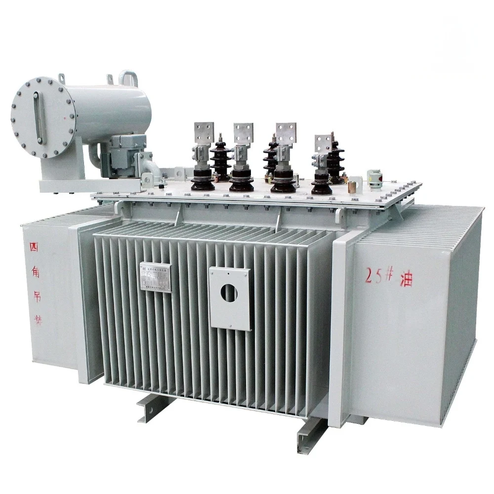
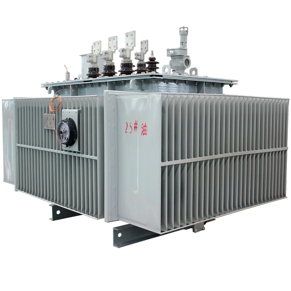
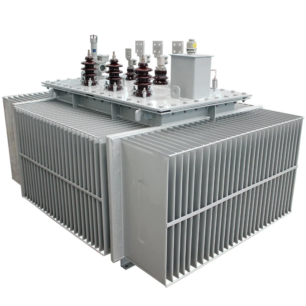
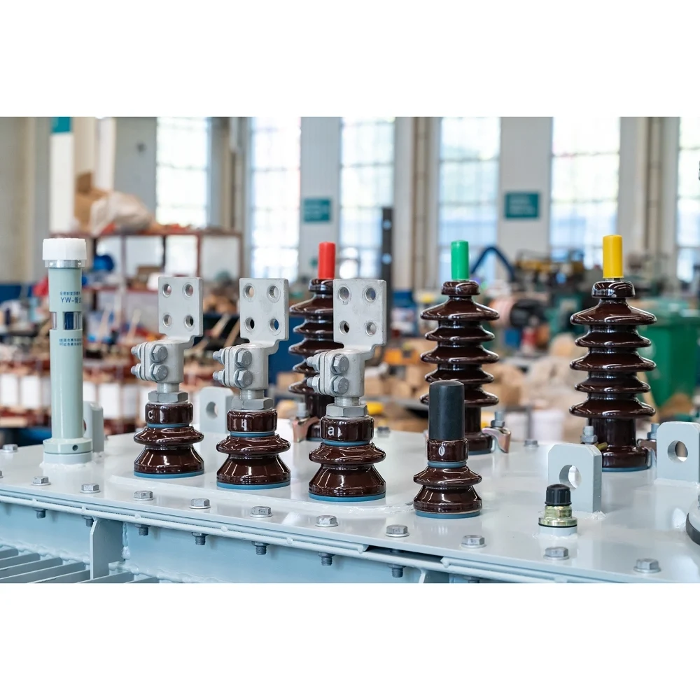
Customizable 10kV SH15/SH21/SH25 Oil-immersed Amorphous Alloy Core Distribution Transformer
Overview
The Kete oil-immersed amorphous alloy transformer is a new type of energy-saving power equipment. It combines the low-loss characteristics of amorphous alloy materials with the excellent cooling and insulation performance of the oil-immersed structure. It is equipped as low coercive force, low loss, good temperature stability and strong protection for thunder and lighting.
Brief introduction
Ⅰ.Brief introduction
1.Standards: IEC 60076, GB/T 1094, GB/T 25446-2010
2.Power Rating: 30KVA-2500 kVA
3.Primary Voltage: 6KV-11KV
4.Secondary Voltage: 0.4 kV or as required
5.Voltage regulation mode: off-circuit tap changing
6.Frequency: 50HZ or 60HZ
7.Type: 3 Phase Electric Power Transformer
8.Connection Type: Dyn11, Yyn0, or per client specification
9.insulation grade: A
10.Cooling method: ONAN
Ⅱ.Working conditions
1.Ambient Temperature: No more than +40℃ No less than -25℃, The monthly average temperature is no more than +30℃, The yearly average temperature is no more than +20℃
2.Altitude: No more than 1000m.
3.Relative air humidity:≤90%
4.installation site: no corrosion gas, No obvious dirt
5.Scope of application: The scope of application is mainly concentrated in scenarios with stable loads, long operating hours, and high requirements for energy efficiency, such as power distribution networks, commercial and civil buildings, new energy supporting facilities, and other fields.
Ⅲ.The tests for oil-immersed transformer
The experimental types of amorphous alloy transformers cover four core directions: basic performance testing, safety and reliability testing, special working condition testing, and material & process testing:
1.Basic Performance Testing
This type of experiment aims to verify whether the core electrical performance of the transformer meets design standards, serving as a core link in product research and development as well as factory inspection.
①No-load Loss and No-load Current Testing
②Load Loss and Short-Circuit Impedance Testing
③Turns Ratio and Polarity Testing
④Insulation Resistance and Dielectric Loss Testing
2.Safety and Reliability Testing
This type of experiment focuses on the safety of transformers under extreme conditions or long-term operation, serving as a key requirement for product finalization and grid access.
①Power Frequency Withstand Voltage Test
②Lightning Impulse Withstand Voltage Test
③Short-Circuit Withstand Capability Test
④Temperature Rise Test
3.Special Working Condition and Environmental Adaptability Testing
Targeted experiments are required for different application scenarios (e.g., plateaus, humid areas, high-altitude regions) or special needs.
①Environmental Adaptability Testing
②Noise Testing
③Partial Discharge Testing
4.Material and Process Verification Testing
The performance of amorphous alloy cores directly affects the overall indicators of transformers, requiring separate testing of materials and manufacturing processes.
①Amorphous Alloy Strip Performance Testing
②Core Winding Process Testing
The experimental types of amorphous alloy transformers must balance electrical performance, safety reliability, environmental adaptability, and material processes, covering the entire process from research and development to factory delivery. Among them, no-load loss testing, short-circuit withstand capability testing, temperature rise testing, and core material performance testing are key differentiators from traditional transformers, directly determining their energy-saving advantages and operational stability.
Ⅳ.Amorphous Alloy Transformer Component Inspection
Amorphous alloy transformers are widely used in power systems due to their advantages such as low loss and energy efficiency. Their component inspection involves multiple core components including iron cores, windings, oil tanks, insulation systems, and cooling systems.
1.Iron Core Inspection
The amorphous alloy iron core is the “heart” of the transformer, and its performance directly affects the loss and efficiency of the transformer. The key inspection aspects include:
①Appearance quality inspection
②Dimensional accuracy inspection
③Iron loss inspection
④Magnetic flux density distribution inspection
⑤Annealing quality inspection
2.Winding Inspection
Windings are the core components for the transformer to realize electrical energy conversion, and their electrical performance and mechanical strength need to be focus on:
①DC resistance inspection
②Insulation resistance inspection
③Dielectric loss factor (tanδ) inspection
④AC withstand voltage test
⑤Partial discharge inspection
⑥Mechanical strength inspection
3.Oil Tank and Structural Component Inspection
①Appearance and tightness inspection
②Dimension and deformation inspection
③Structural strength inspection
4.Insulation System Inspection
The insulation system is crucial for ensuring the safe operation of the transformer, covering solid insulation (such as insulating paper and insulating cardboard) and liquid insulation (such as transformer oil):
①Solid insulation inspection
②Transformer oil inspection
5.Cooling System Inspection
The performance of the cooling system directly affects the heat dissipation effect of the transformer. The inspection contents are as follows:
①Radiator / cooler inspection
②Fan and oil pump inspection
③Temperature control device inspection
Ⅴ.Certificate: CE, UL, ISO, SGS, CCC
Structural Features
Ⅰ.Product features
Amorphous alloy transformers are a type of power transformer that uses amorphous alloy materials as their core. Amorphous alloys are formed by directly cooling molten metal alloys into a solid state through rapid solidification technology (with a cooling rate as high as one million degrees Celsius per second), resulting in an amorphous structure with disordered atomic arrangement. Their core characteristics directly determine the performance of the transformer:
1.Low hysteresis loss: Due to the disordered atomic arrangement of amorphous alloys, the resistance to domain rotation and displacement during magnetization is extremely small. The area of the hysteresis loop is much smaller than that of silicon steel sheets (only 1/5 – 1/10 of traditional silicon steel sheets), which is the core reason for its energy efficiency.
2.High magnetic permeability: High magnetization can be achieved under weak magnetic fields, which reduces the excitation current and lowers the no-load loss.
3.Mechanical properties: Amorphous alloys have high hardness (about 2 – 3 times that of silicon steel sheets) but are highly brittle and prone to fragmentation during processing. Therefore, the core is usually manufactured using a winding process rather than a laminated structure.
4.Corrosion resistance: A natural oxide film forms on the surface, providing better corrosion resistance than ordinary silicon steel and reducing the risk of core rusting.
Ⅱ.Product Advantages
Advantages of Amorphous Alloy Transformers:
1.Extremely low no-load loss: The no-load loss of amorphous alloy core transformers is reduced by approximately 70% – 80% compared to traditional silicon steel sheet transformers. For example, the no-load loss of a 10kV class 500kVA amorphous alloy transformer is about 300W, while that of a silicon steel sheet transformer of the same class is approximately 1200W – 1500W.
2.Suitable for light-load operation: In areas with low grid load rates such as rural areas and suburban districts, the energy-saving effect is particularly prominent. Long-term operation can significantly reduce electricity expenses.
3.Small no-load current: It is usually more than 50% lower than that of silicon steel sheet transformers, which reduces the reactive power loss of the power grid and helps improve the grid power factor.
4.Slightly lower noise: Due to the smaller magnetostriction coefficient of amorphous alloy materials, the operating noise is 3dB – 5dB lower than that of traditional transformers, making them more suitable for noise-sensitive areas (such as residential areas and hospitals).
5.Compact structure: The core adopts a wound structure, and its volume is equivalent to or slightly smaller than that of a silicon steel sheet transformer with the same capacity, facilitating installation and layout.
Product structure
Oil-immersed amorphous alloy transformers are high-efficiency and energy-saving power equipment. Their core advantage lies in the use of amorphous alloy core materials, which have the characteristics of low loss and high magnetic permeability.
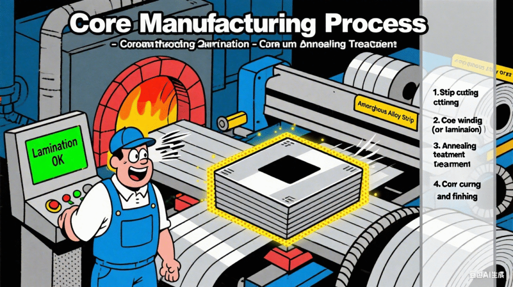
Ⅰ.Core Manufacturing Process
The core is a key component that determines the energy-saving performance of the transformer. Amorphous alloy strips are highly brittle and easy to break, so the manufacturing process must be extremely precise.
1.Strip cutting
2.Core winding (or lamination)
3.Annealing treatment
4.Core curing and finishing
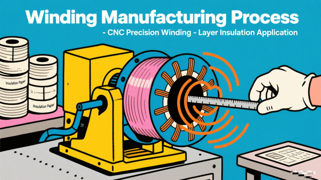
Ⅱ.Winding Manufacturing Process
The winding is the conductive component of the transformer, which must meet the requirements of insulation strength, mechanical strength, and heat dissipation performance.
1.Conductor pre-treatment
2.Winding drying and curing
3.Winding insulation testing
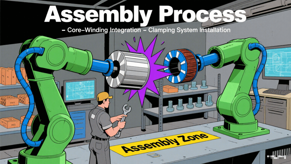
Ⅲ.Core Assembly Process
Core assembly is a crucial link in combining the core, windings, and related components into an integrated whole. It is necessary to ensure accurate positioning of components and reliable insulation.
1.Core and winding assembly
2.Lead connection
3.Core drying
4.Overall core inspection
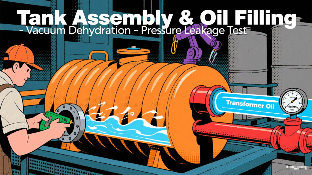
Ⅳ.Oil Tank Assembly and Oil Filling Process
The oil tank is the outer shell of the transformer, which must satisfy the functions of sealing, heat dissipation, and mechanical protection.
1.Oil tank pre-treatment
2.Accessory installation
3.Core placement into the tank
4.Vacuum oil filling
5.Seal detection
Ⅴ.Finished Product Testing and Factory Process
After the transformer production is completed, strict tests are required to verify whether its performance meets the standards.
1.Routine tests
2.Type tests (conducted by sampling)
3.Appearance and packaging

Specification
Customizable 10kV SH15/SH21/SH25 oil-immersed amorphous alloy core distribution transformer
| Rated Capacity | H.V. | L.V. | Connection symbol | No-load loss(w) | On-load loss(w) | Short circuit impedance | ||||
|---|---|---|---|---|---|---|---|---|---|---|
| S15 | S21 | S25 | S15 | S21 | S25 | |||||
| 30 | 6 6.3 10 10.5 11 |
0.4 | Dyn11 Yyn0 |
33 | 33 | 25 | 630/660 | 535/510 | 510/480 | 4 |
| 50 | 43 | 43 | 35 | 910/870 | 780/745 | 735/700 | ||||
| 63 | 50 | 50 | 40 | 1090/1040 | 930/890 | 880/840 | ||||
| 80 | 60 | 60 | 50 | 1310/1250 | 1120/1070 | 1060/1010 | ||||
| 100 | 75 | 75 | 60 | 1580/1500 | 1350/1285 | 1270/1215 | ||||
| 125 | 85 | 85 | 70 | 1890/1800 | 1615/1540 | 1530/1450 | ||||
| 160 | 100 | 100 | 80 | 2310/2200 | 1975/1880 | 1870/1780 | ||||
| 200 | 120 | 120 | 95 | 2730/2600 | 2330/2225 | 2210/2100 | ||||
| 250 | 140 | 140 | 110 | 3200/3050 | 2735/2610 | 2590/2470 | ||||
| 315 | 170 | 170 | 135 | 3830/3650 | 3275/3120 | 3100/2950 | ||||
| 400 | 200 | 200 | 160 | 4520/4300 | 3865/3675 | 3660/3480 | ||||
| 500 | 240 | 240 | 190 | 5410/5150 | 4625/4400 | 4380/4170 | ||||
| 630 | 320 | 320 | 250 | 6200 | 5300 | 5020 | 4.5 | |||
| 800 | 380 | 380 | 300 | 7500 | 6415 | 6075 | ||||
| 1000 | 450 | 450 | 360 | 10300 | 8800 | 8340 | ||||
| 1250 | 530 | 530 | 425 | 12000 | 10260 | 9720 | ||||
| 1600 | 630 | 630 | 500 | 14500 | 12400 | 11745 | ||||
| 2000 | 720 | 710 | 550 | 18300 | 14800 | 14000 | 5 | |||
| 2500 | 865 | 860 | 670 | 21200 | 16300 | 15450 | ||||
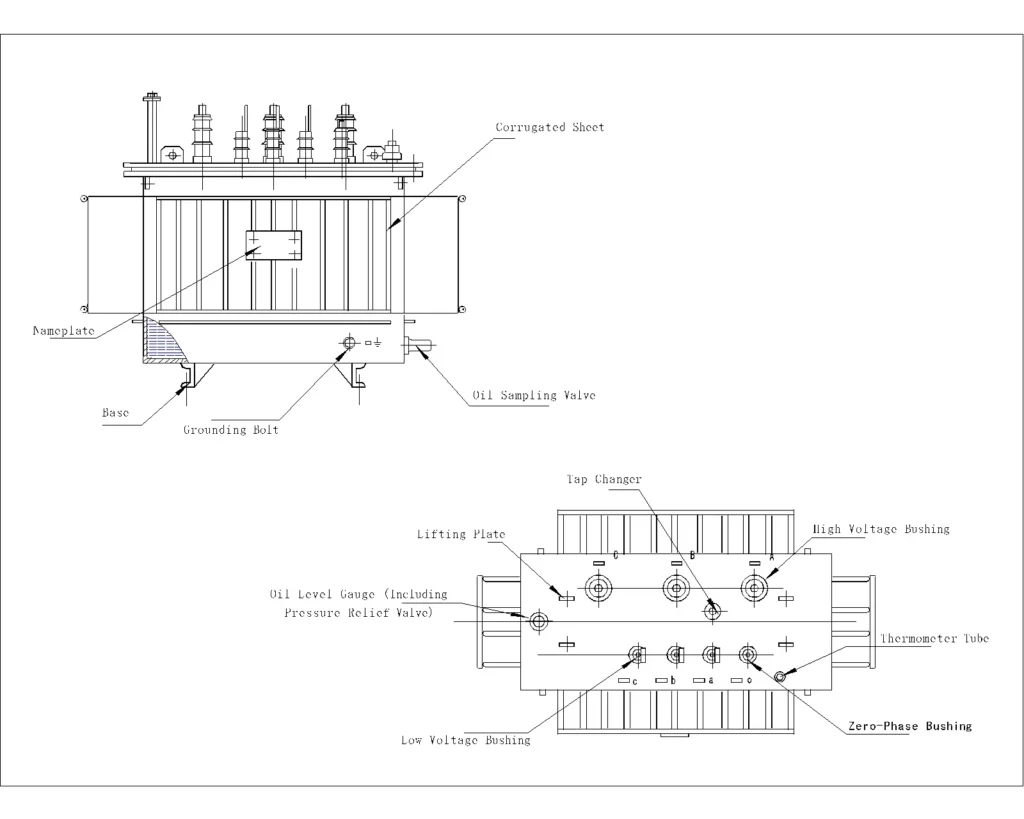
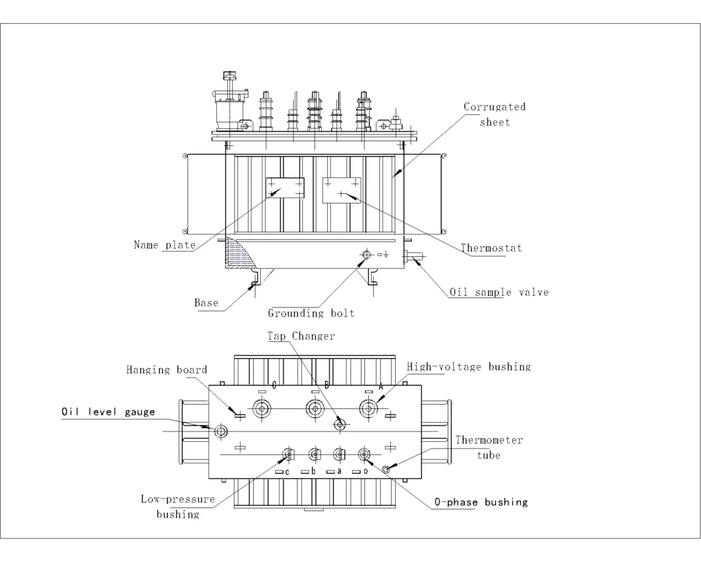
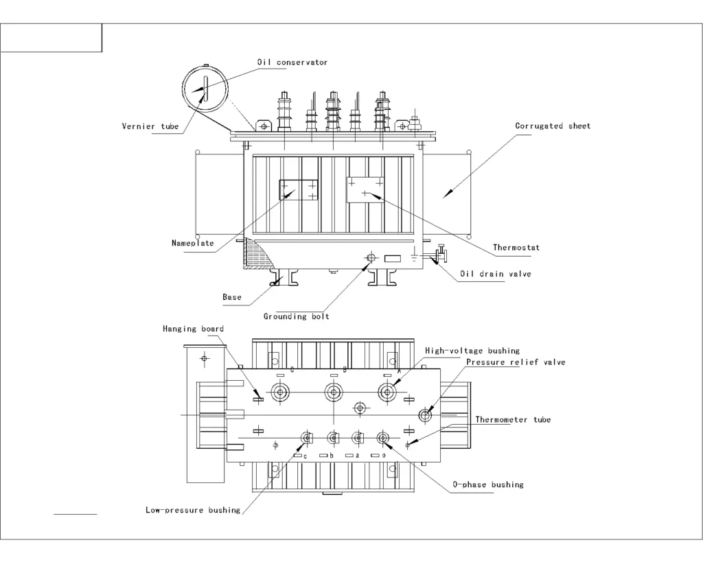
FAQs
Ⅰ.Basic Maintenance Service
1.What are the rated voltage and power of the Kete oil-immersed amorphous alloy transformer?
①Primary Voltage (High Voltage Side): Typically range from 1 kV to 66 kV, with common ratings like 6kV, 10 kV, 11KV, 20KV, 33 kV, 34.5KV, 35KV
②Secondary Voltage (Low Voltage Side): Common secondary voltage ratings include:
·400 V (0.4 kV) for industrial and residential supply
·11 kV or 33 kV
③Customization: Transformers can be designed for specific applications. If you have specific power requirements or voltage needs, we can specially design and customize transformers to meet your demands.
2.What type of cooling system does the Kete oil-immersed amorphous alloy transformer use?
Kete oil-immersed amorphous alloy transformers mainly adopt two common cooling methods: ONAN and ONAF.
①Scope of Application of ONAN
·Transformers with small capacity
Typical applicable capacity: Usually used for transformers of 10kV class with 500kVA and below, and 35kV class with 1000kVA and below.
Reason: Small-capacity transformers have low losses (small heat generation), and natural heat dissipation can meet the temperature rise requirements, with a simple structure and low cost.
·Scenarios with loose installation environment
Suitable for outdoor open spaces, well-ventilated indoor distribution rooms, or areas with low ambient temperatures.
If installed in enclosed spaces (such as basements), additional evaluation of heat dissipation conditions is required, and the cooling method may need to be upgraded.
·Transformers with low load rate or intermittent operation
For transformers that are in a light load state for a long time (load rate < 50%), the heat dissipation capacity of ONAN is sufficient, without wasting energy consumption from forced cooling.
②Scope of Application of ONAF
·Medium and large capacity transformers
Typical applicable capacity: 10kV class with 800kVA and above, 35kV class with 1600kVA and above for small and medium-sized transformers.
Reason: Medium and large-capacity transformers have high losses (large copper loss and iron loss), and natural heat dissipation cannot meet the temperature rise limit, so fans are needed to assist in enhancing heat dissipation.
·Transformers with high load rate or continuous operation
Suitable for scenarios with long-term full-load operation or large load fluctuations (needing to cope with short-term overload), such as main transformers in industrial plants and hub transformers in urban distribution networks.
·Environments with limited heat dissipation conditions
If the transformer is installed in a poorly ventilated indoor environment or in areas with high ambient temperatures (such as tropical regions), ONAF can make up for the deficiency of natural heat dissipation through forced air cooling, avoiding excessive oil temperature that affects service life.
3.How does the cooling system of the Kete oil-immersed amorphous alloy transformer affect its performance under different climatic conditions?
The impact of ONAN (Oil-Immersed Natural Air Cooling) and ONAF (Oil-Immersed Forced Air Cooling) cooling systems of Kete oil-immersed amorphous alloy transformers on performance under different climatic conditions is as follows:
①Impact of High-Temperature Climate
·ONAN Cooling System: When the ambient temperature exceeds 40°C, the heat dissipation efficiency of the ONAN cooling system decreases significantly, potentially dropping to approximately 60%. This is because high temperatures reduce the viscosity of the oil, weakening its fluidity and thus lowering the efficiency of natural convection heat dissipation. At this point, the winding temperature of the transformer rises rapidly, accelerating insulation aging. According to the Arrhenius law, the insulation life is halved for every 8°C increase in temperature. Meanwhile, high temperatures cause a decrease in the magnetic permeability of silicon steel sheets and an increase in eddy current losses, reducing energy efficiency. The transformer may need to be derated; otherwise, there are risks of insulation damage and fire.
·ONAF Cooling System: In high-temperature environments, the cooling effect of the fans in the ONAF cooling system diminishes. Although heat dissipation can be enhanced by adding auxiliary cooling equipment, the overall performance is still affected to a certain extent. However, compared to the ONAN cooling system, the ONAF system, with active heat dissipation by fans, achieves higher heat dissipation efficiency under the same high-temperature conditions. It can better control the transformer’s winding temperature and delay insulation aging.
②Impact of Low-Temperature Climate
·ONAN Cooling System: In low-temperature environments, such as temperatures below -30°C, the viscosity of transformer oil increases sharply, leading to greater circulation resistance. This may cause heat dissipation to stagnate, or even result in oil solidification (the pour point of transformer oil is approximately -45°C). In addition, dissolved water in the oil may turn into suspended ice crystals, increasing the risk of partial discharge. During cold startup, mechanical stress may cause welds or insulation to crack due to brittleness. Therefore, in extremely low temperatures, preheating to above 0°C is required before commissioning.
·ONAF Cooling System: In low-temperature environments, apart from the issue of increased oil viscosity similar to that of ONAN, the ONAF cooling system also faces the risk of fan icing. This can affect the normal operation of the fans and further impair heat dissipation efficiency.
③Impact of High-Humidity and Salt-Spray Climate
·ONAN Cooling System: In high-humidity environments with humidity exceeding 90%, the moisture content of insulation paper increases, causing the dielectric strength to decrease by approximately 30% and reducing the transformer’s insulation performance. In salt-spray environments, winding joints are corroded, increasing contact resistance and leading to local overheating, which affects the transformer’s normal operation and service life.
·ONAF Cooling System: High-humidity and salt-spray climates affect the ONAF cooling system similarly to ONAN, mainly causing insulation performance degradation and component corrosion. However, since the ONAF cooling system is equipped with rotating components such as fans, in high-humidity environments, additional attention must be paid to preventing issues such as moisture-induced short circuits in fan motors.
4.What is the main basis for choosing between ONAN and ONAF cooling methods for kete oil-immersed amorphous alloy transformers?
The choice between ONAN (Oil Natural Circulation and Air Natural Cooling) and ONAF (Oil Natural Circulation and Air Forced Cooling) cooling methods for Kete oil-immersed amorphous alloy transformers is corely based on the matching between the transformer’s heat dissipation requirements and actual heat dissipation conditions. Specifically, it can be comprehensively judged from the following 5 key dimensions:
①Transformer Rated Capacity and Heat Generation from Losses
This is the most fundamental basis. The heat generated by a transformer mainly comes from copper losses (load losses) and iron losses (no-load losses). The larger the capacity, the higher the losses and the stronger the heat dissipation demand:
·Small-capacity transformers (low loss):
When the rated capacity is small (e.g., ≤500kVA for 10kV class, ≤1000kVA for 35kV class), the heat generated by losses is small. Heat can be dissipated through the natural convection of transformer oil (hot oil rises, cold oil falls) and the natural convection between the casing/radiator and air, without the need for additional cooling equipment. Therefore, ONAN is preferred.
·Medium and large-capacity transformers (high loss):
When the capacity exceeds the above range (e.g., ≥800kVA for 10kV class, ≥1600kVA for 35kV class), losses increase significantly, and the natural heat dissipation rate cannot match the heat generation. This may cause the oil temperature to exceed national standard limits (usually top oil temperature rise ≤55K or 60K). In such cases, fans must be used to force air flow and accelerate heat dissipation, so ONAF is chosen.
②Operating Load Characteristics
The actual load rate and operation mode of the transformer directly affect heat dissipation requirements:
·Low load rate or intermittent operation:
If the transformer operates at light load for a long time (load rate < 50%) or only runs during short-term peak periods (e.g., rural distribution transformers), even if its capacity is slightly larger, the actual heat generation is low. The natural heat dissipation capacity of ONAN can meet the demand, and there is no need to waste energy on fans. Thus, ONAN is selected.
·High load rate or continuous full-load operation:
For transformers in industrial parks, urban core distribution networks, and other equipment that operate at full load for a long time or have large load fluctuations (needing to cope with short-term overload), heat generation remains high. ONAN cannot meet the heat dissipation requirements, so ONAF’s forced air cooling via fans is necessary. Even during overload, fans can enhance heat dissipation capacity (usually supporting 10%-20% short-term overload). Hence, ONAF is chosen.
③Installation Environment and Heat Dissipation Conditions
Environmental factors directly affect the efficiency of natural heat dissipation, and cooling methods need to be adjusted according to scenarios:
·Well-ventilated and low-temperature environments:
If the transformer is installed in an open outdoor area, high-altitude regions (low air density but good ventilation), or cold areas, the efficiency of natural convection heat dissipation is high. Even if the capacity is close to the critical value, ONAN can be prioritized.
·Poorly ventilated and high-temperature environments:
If installed in enclosed distribution rooms, basements, tropical regions, or industrial environments with heavy dust/oil pollution, natural heat dissipation is hindered. Even with a slightly smaller capacity, oil temperature may rise excessively due to poor heat dissipation conditions. In such cases, upgrading to ONAF is necessary to compensate for environmental defects through forced air flow by fans.
④Cost and Maintenance Requirements
There are significant differences in initial costs and operation/maintenance costs between the two cooling methods:
·Advantages of ONAN:
It has no fans or control circuits, resulting in a simpler structure. The initial procurement cost is low (5%-10% lower than ONAF of the same capacity), and there is no need for motor maintenance, making long-term operation and maintenance costs almost zero. It is suitable for scenarios sensitive to cost and with limited maintenance resources (e.g., rural power grids, small user transformers).
·Disadvantages and necessity of ONAF:
It requires additional configuration of fans, thermostats, and power circuits, leading to higher initial costs. Fan motors need regular inspection (dust cleaning, bearing lubrication), involving certain maintenance workload and energy consumption (fan power is usually tens to hundreds of watts). However, for medium and large-capacity transformers or those with insufficient heat dissipation conditions, these costs must be borne to ensure safe operation. Thus, ONAF is a “necessary choice” rather than a “cost-priority choice.”
5.How long is the service life of Kete oil-immersed amorphous alloy transformers?
According to international standards (such as IEC 60076), the design life of Kete oil-immersed amorphous alloy transformers is usually calculated as 20 years. This is the expected service life under the ideal condition of “normal operating conditions + regular maintenance”, which refers to the time it takes for core components (iron core, windings, insulating oil) to age to a critical state within the design parameters.
Practical industry reference range: In actual power grid or industrial applications, it is a dynamic indicator affected by multiple factors such as design standards, operating conditions, and maintenance levels. The service life of transformers can generally reach 20-40 years.
6.What are the factors that affect the service life of Kete amorphous alloy oil-immersed transformers?
The core limiting factor for Kete transformer lifespan is the aging rate of its insulation system (including winding insulation paper, insulating oil, and insulating components), which is determined by the following factors:
①Operating Temperature (the most critical factor)
·The aging rate of insulating materials, especially paper insulation, has an exponential relationship with temperature. According to the “thermal aging law,” the insulation lifespan is halved for every 6-8℃ increase in temperature.
·During normal operation, the maximum top oil temperature rise limit for oil-immersed transformers is typically 55K (ambient temperature + 55℃). Long-term operation at excessive temperatures (e.g., top oil temperature exceeding 80℃) accelerates the embrittlement of insulation paper and the cracking of insulating oil, significantly shortening the lifespan.
For example, if a transformer operating at full load or overload for a long time experiences cooling system failure leading to overheating, its lifespan may be reduced from 30 years to less than 15 years.
②Quality and Condition of Insulating Oil
·Insulating oil primarily functions for insulation and heat dissipation, and its performance degradation directly affects the lifespan of the insulation system.
·Excessive moisture, increased acid value, accumulated impurities, or sludge formation in the oil reduce insulation strength and accelerate winding corrosion and aging.
·Failure to regularly filter, regenerate, or replace the oil (it is generally recommended to test every 3-5 years and replace or regenerate every 10-15 years) will cause premature failure of the insulation system.
③Materials of Insulating Paper / Cardboard
·Ordinary wood pulp insulating paper: Its temperature resistance class is Class A (maximum allowable temperature: 105℃). It is prone to hydrolysis in environments above 65℃, with a service life of approximately 15-20 years.
·Full cellulose insulating paper: It has better hydrolysis resistance and oxidation resistance, and its service life can be extended to 25-30 years.
·High-temperature resistant insulating paper (e.g., NOMEX paper): Its temperature resistance class reaches Class H (180℃). It can withstand higher temperature fluctuations, making it suitable for high-temperature or frequent overload scenarios, with a service life of over 30 years.
④Load Characteristics and Operating Conditions
·Long-term high load rates, frequent overloads, or short-circuit impacts cause winding overheating and increased mechanical stress, accelerating insulation fatigue:
Rural power grid or industrial transformers that frequently withstand short-term overloads (e.g., motor startup impacts) are prone to insulation aging in windings due to thermal cycles and mechanical vibrations.
·Short-circuit faults (e.g., line short circuits causing transformers to bear huge short-circuit currents) may result in winding deformation and insulation damage. Even after repair, hidden dangers may remain, shortening the remaining lifespan.
⑤Environmental Conditions
·The installation environment directly affects the aging rate of insulation and components.
·Humid, high-temperature, or highly polluted environments (with dust or chemically corrosive gases) accelerate insulation moisture absorption, oil degradation, and rusting of metal parts.
·In high-altitude areas (where air is thin and heat dissipation is poor), insufficient heat dissipation may lead to overheating if the transformer is not specially designed.
Locations with strong vibrations (e.g., industrial workshops near pumps or fans) exacerbate winding loosening and insulation wear.
⑥Maintenance Level
·Lack of regular inspections (such as oil quality testing, insulation resistance testing, and partial discharge detection) prevents early faults from being identified, allowing minor issues to evolve into major defects.
·Unrepaired faults in cooling systems (fans, oil pumps) reduce heat dissipation efficiency and cause temperature rise.
·Neglected maintenance of accessories like bushings and tap changers may trigger local overheating or insulation breakdown, indirectly affecting the overall lifespan.
⑦Manufacturing Process
·Excessive burrs on the edges of the iron core and misaligned laminations will lead to increased no-load loss and local overheating, which indirectly accelerates insulation aging; if the iron core annealing process fails to meet standards, it will cause a decrease in the magnetic permeability of the iron core and an increase in loss.
·Irregular arrangement of winding wires will result in insufficient tightness of the windings, increased vibration during operation, and wear of the insulating paper; poor winding impregnation process will lead to air gaps inside the windings, causing partial discharge and damaging the insulation.
·Sand holes at the welding joints of the oil tank and inadequate tightness testing will cause oil leakage during operation; unreasonable radiator design and insufficient heat dissipation area will lead to high top oil temperature of the transformer and accelerate insulation aging.
7.How to maintain transformers to maximize the service life of Kete oil-immersed amorphous alloy transformers?
8.What type of oil is used in Kete oil-immersed transformers? What advantages does this type of oil have?
Mineral insulating oil in Kete oil-immersed transformers plays multiple crucial roles in ensuring the safe and stable operation of transformers.
①Excellent Insulating Performance for Electrical Safety
·High Breakdown Strength: The breakdown voltage of mineral insulating oil is typically above 30kV (high-quality products can reach over 50kV), far exceeding that of air (approximately 3kV/mm). This effectively isolates conductors at different potentials and prevents short-circuit faults caused by insulation breakdown.
·Low Dielectric Loss and High Volume Resistivity: It has a small dielectric loss factor (tanδ), resulting in low energy loss under electric fields and reduced heat generation. Meanwhile, its high volume resistivity (usually >10¹⁴Ω・cm) minimizes leakage current, further enhancing insulation reliability.
·Filling Insulation Gaps: Solid insulating materials such as insulating paper and cardboard inside transformers have tiny pores. Mineral insulating oil can penetrate these pores, fill air gaps, avoid partial discharge caused by air ionization, and improve the overall dielectric strength of the insulation system.
②Efficient Heat Dissipation to Maintain Stable Equipment Temperature Rise
·Good Thermal Conductivity: Its thermal conductivity is approximately 0.12-0.15 W/(m・K), much higher than that of air (about 0.026 W/(m・K)), enabling it to quickly absorb heat generated by windings and iron cores.
·Convection Circulation Cooling: Heated insulating oil reduces in density, naturally rises to the radiator at the top of the transformer, exchanges heat with air through the radiator, cools down, and sinks, forming a circulation to continuously conduct heat out of the equipment.
·Synergy with Cooling Systems: In large transformers, mineral insulating oil can work with forced oil circulation cooling systems (such as oil pumps and cooling fans) to further enhance heat dissipation efficiency, meeting the needs of high-load operation.
③Strong Chemical Stability to Extend Equipment Lifespan
·Excellent Oxidation Resistance: Refined mineral insulating oil (e.g., derived from naphthenic or paraffinic crude oil) contains few impurities such as sulfur and nitrogen. It is not easily oxidized at high temperatures to form acids, colloids, or sludge, reducing corrosion and blockage of insulating materials.
·Low Volatility: It has a high boiling point and low volatility, so it is not prone to oil reduction or performance degradation due to volatilization during long-term operation, reducing maintenance frequency.
·Good Compatibility with Solid Insulation: It is well compatible with materials commonly used in transformers, such as cellulose paper and insulating cardboard, without chemical reactions that cause material aging, jointly maintaining the stability of the insulation system.
④Arc Quenching and Protection to Enhance Operational Safety
·Arc Quenching Function: When an arc is generated, the oil decomposes into gases such as hydrogen and methane, which can absorb arc energy. At the same time, the flow of oil can cool the arc area, quickly extinguishing the arc and preventing fault expansion.
·Isolating Air and Moisture: The oil layer covers the surface of internal components, isolating oxygen and moisture in the air, avoiding moisture-induced rust of metal components such as iron cores and windings, and reducing the risk of insulation deterioration.
·Fault Diagnosis Carrier: Insulating oil generates characteristic gases (such as acetylene and hydrogen) during faults. Through Dissolved Gas Analysis (DGA) technology, potential faults can be detected in advance, providing a basis for equipment condition assessment and maintenance.
⑤Advantages in Economy and Practicality
·Controllable Cost: Mineral insulating oil has wide raw material sources (based on petroleum refining), mature production processes, and relatively low prices, making it suitable for large-scale applications in various transformers (from distribution transformers to ultra-high voltage transformers).
·Convenient Maintenance: During normal operation, only regular monitoring of oil quality (such as moisture, dielectric loss, and breakdown voltage) is required. If necessary, filtration and regeneration treatments can restore its performance, with maintenance costs lower than some synthetic insulating oils.
·Strong Adaptability: It can maintain stable performance over a wide temperature range (e.g., good fluidity at low temperatures and resistance to deterioration at high temperatures), adapting to the operational needs of different climate regions.
Mineral insulating oil provides comprehensive operational protection for transformers through its four core roles: insulation, heat dissipation, chemical stability, and arc quenching protection. It is an indispensable key material in power systems. Its performance is directly related to the lifespan, efficiency, and safety of transformers, so it still dominates the power industry (although synthetic insulating oils are increasingly used in specific scenarios, mineral oil remains one of the most cost-effective choices).
9.What protective measures does the Kete oil-immersed transformer have against overload, overheating, and short circuits?
Kete oil-immersed transformers typically adopt multi-level protection measures, covering internal self-protection design, external monitoring devices, and relay protection systems.
①Protection Measures Against “Overload”
Overload refers to the situation where the transformer’s load current exceeds the rated value for a long or short period, which may cause winding overheating and accelerated insulation aging. The main protection measures include:
·Overload Protection (Relay Protection System)
Principle: Load current of the transformer is monitored by current transformers. When the current exceeds a certain multiple of the rated value (e.g., 1.2~1.5 times) and lasts for a set threshold, the protection action is triggered.
·Internal Thermal Protection Design: Including winding Conductor Selection and heat Dissipation Structure Optimization: Natural heat dissipation capacity is enhanced by increasing the oil tank volume and optimizing the layout of cooling fins, mitigating temperature rise during overload.
②Protection Measures Against “Overheating”
Overheating may be caused by overload, excessive core loss, or cooling system failures, requiring real-time monitoring and rapid response:
·Temperature Monitoring Devices
Oil Temperature Thermometer: Directly measures the upper oil temperature in the tank. An alarm is issued when the oil temperature exceeds 85°C (typical set value).
Winding Thermometer: Simulates the winding hot-spot temperature (combining oil temperature and load current). Protection is triggered when the hot-spot temperature exceeds 105°C.
Optical Fiber Temperature Measurement: In large transformers, optical fiber sensors are used to directly measure hot-spot temperatures of windings or cores, offering higher accuracy and faster response.
·Cooling System Protection
Forced Cooling Assistance: Larger-capacity transformers are equipped with forced oil circulation air cooling (OFAF) or water cooling systems. These systems automatically start when oil temperature rises to enhance heat dissipation; if the cooling system fails (e.g., fan stops), an alarm is triggered or the load is reduced.
Buchholz Relay: Light gas action may occur when high oil temperature causes oil decomposition and generates a small amount of gas, issuing an alarm to prompt inspection of overheating causes.
·Over-Temperature Trip Protection
When the temperature continues to rise to a dangerous level (e.g., oil temperature exceeds 95°C or winding hot-spot temperature exceeds 120°C), the protection system directly cuts off the transformer power supply to prevent insulation breakdown.
③Protection Measures Against “Short Circuit”
Short circuits (including internal winding short circuits and external outlet short circuits) generate massive currents that may instantly damage the transformer, requiring rapid fault isolation:
·Differential Protection (Main Protection)
Principle: Based on the principle that “current flowing into the transformer equals current flowing out,” current difference is measured by current transformers on both sides. An internal short circuit is determined when the differential current exceeds the set value.
Features: It acts rapidly (usually within tens of milliseconds) and can effectively distinguish between internal short circuits and external faults, serving as the core of transformer short-circuit protection.
·Buchholz Protection (Exclusive to Internal Short Circuits)
Heavy Gas Action: When an internal winding short circuit occurs, high temperatures from the short-circuit current cause intense oil decomposition, generating a large amount of gas. This pushes the Buchholz relay to act, triggering an instantaneous trip to cut off the power supply and prevent fault expansion.
Application Scenario: Particularly suitable for internal faults such as inter-turn or inter-layer winding short circuits, serving as an important supplement to differential protection.
·Overcurrent Protection (Backup Protection)
External Short Circuit Protection: When an external short circuit occurs (e.g., outlet short circuit), overcurrent protection detects the overcurrent and trips with a delay (the delay must avoid the impact duration of the short-circuit current), preventing the transformer from enduring long-term short-circuit currents.
Instantaneous Overcurrent Protection: For close-range external short circuits, instantaneous overcurrent protection can trip without delay to quickly isolate the fault.
·Current Limiting Measures
Short-Circuit Impedance Design: Windings are designed with a specific short-circuit impedance to limit the amplitude of short-circuit currents, reducing mechanical stress on windings and cores caused by short-circuit impacts.
Winding Mechanical Reinforcement: A robust winding structure (e.g., reinforced insulation binding, support strip fixation) is adopted to enhance mechanical strength against short-circuit impacts.
④Comprehensive Protection and Auxiliary Measures
·Grounding Protection: The transformer neutral point is grounded or grounded via an arc suppression coil. In case of a single-phase ground short circuit, zero-sequence current protection detects the fault and trips to prevent overvoltage damage to equipment.
·Backup Protection Coordination: Overload protection, overcurrent protection, etc., act as backups to provide safeguards when main protection fails, forming a multi-layered defense of “main protection + backup protection.”
·Online Monitoring System: Intelligent transformers are equipped with condition monitoring devices that collect real-time data on oil temperature, oil level, gas composition, partial discharge, etc. Potential faults are predicted through data analysis, enabling early warning of short-circuit or overheating risks.
10.What aspects of Kete oil-immersed transformers can be customized?
Kete oil-immersed transformers can be customized in multiple aspects to meet the specific needs of different customers.
①Rated Power and Transformation Ratio: According to the customer’s power consumption requirements, the rated power and transformation ratio of the transformer can be adjusted to ensure the output of appropriate voltage and meet the needs of different loads.
②Overall Dimensions: If the customer’s installation space is limited, manufacturers can customize transformers with special dimensions based on actual conditions to enable them to better adapt to the installation environment.
③Accessories and Wiring Methods: Corresponding accessories such as junction boxes, temperature probes, and gas relays can be provided according to customer requirements, and reasonable wiring methods can be designed to facilitate customers’ installation and use.
④Winding Material: Some oil-immersed transformers offer two winding materials, full copper and full aluminum, for users to choose from. Full-copper transformers have good electrical conductivity and thermal conductivity, which can reduce resistance and temperature rise; full-aluminum transformers, on the other hand, are lighter in weight and have excellent corrosion resistance.
⑤Insulation Material: High-temperature-resistant insulation materials can be selected to meet the insulation performance requirements under special environments or operating conditions, thereby improving the reliability and service life of the transformer.
⑥Protection Level: For some special application environments, such as high-temperature, high-humidity, polluted areas, or offshore platforms, the protection level of the transformer can be improved through special design to make it adapt to harsh operating environments.
⑦Heat Dissipation Method: According to the capacity and usage environment of the transformer, the heat dissipation design can be optimized. For example, special oil channel design, increasing the number of cooling fins, or adopting forced air cooling can be used to improve heat dissipation efficiency and reduce the temperature rise of the transformer.
⑧Winding Structure: For instance, for low-voltage and high-current windings, copper foil winding can be adopted. On one hand, it reduces the transverse leakage flux of the winding to decrease eddy current loss; on the other hand, it improves the transformer’s ability to withstand sudden short circuits.
Ⅱ.After-sales maintenance
1.What is included in Kete's warranty coverage during the warranty period? And how are the costs borne?
Our company’s warranty coverage includes performance failures caused by material defects or manufacturing process issues, such as cabinet water leakage, insulation failure, abnormal switch operation, etc.
We provide spare parts for maintenance free of charge, and will dispatch technical personnel for on-site inspection and repair if necessary, with travel expenses borne by the supplier.
2.Will Kete provide guidance documents for installation?
For large transformers that require the removal of some accessories to fit into containers, we will provide an installation video and an electronic version of the installation instructions.
3.If maintenance is required and spare parts are purchased from Kete, how long will it take for the spare parts to arrive?
If the customer needs to purchase spare parts from our company, the goods can generally be shipped within 2-7 days.
4.How to handle emergency maintenance requests, and what is the typical response time?
24/7 technical support hotline, ensuring a fault time of ≤ 2 hours.
5.What kind of after-sales support can Kete provide, including troubleshooting and maintenance services?
During the warranty period, regular return visits (once every 3 months) will be conducted to provide operation status testing and maintenance recommendations.
After the warranty period expires, lifelong maintenance services at cost price and spare parts supply can be provided.
6.Can Kete provide options for service contracts or extended warranty periods?
Yes, we can. Generally, the warranty period for our products is one year. If an extension of the warranty period is required, we will increase the price by a certain profit margin based on the existing price accordingly.
7.How should the oil in Kete oil-immersed transformers be inspected, maintained?
The insulating oil for oil-immersed amorphous alloy transformers (referred to as “transformer oil”) is a core medium ensuring the safe operation of transformers, with three major functions: insulation, cooling, and arc extinguishing. Deterioration in its performance may lead to insulation failure, overheating, or even explosions of transformers. Therefore, regular testing and scientific maintenance are crucial.
①Core Testing Items for Transformer Oil
Testing of transformer oil should combine regular preventive tests and operational condition monitoring. Key items are as follows:
·Routine Physicochemical Property Testing (Basic Indicators): Appearance and Odor, moisture Content (Trace Water), kinematic Viscosity, acid Value
·Electrical Performance Testing (Key Safety Indicators): Breakdown Voltage, dielectric Loss Factor (tanδ)
·Analysis of Dissolved Gases in Oil
Principle: Internal faults in transformers (such as local overheating or arc discharge) generate characteristic gases (e.g., H₂, CH₄, C₂H₂, CO), which dissolve in the oil. The type of fault can be judged by detecting the composition and concentration of these gases.
Testing Frequency: Once after new installation or major repair; for operating transformers, once every 3 months for 330kV and above, and once every 6 months for 110kV-class.
·Other Specialized Tests
Antioxidant content: For oil added with T501 antioxidant, its content should be tested (usually maintained at 0.3%~0.5%) and supplemented if insufficient.
Sludge and sediment: Sludge may form in oil after long-term operation, affecting heat dissipation and insulation. It can be detected by centrifugation or filtration.
②Daily Maintenance Measures for Transformer Oil
·Oil Storage and Replenishment Management
Oil Storage Requirements: Transformer oil should be stored in sealed dedicated oil tanks to avoid direct sunlight, moisture, and impurity contamination. New oil can only be used after passing inspection.
Oil Replenishment Principles: Before replenishment, confirm that the brand and performance indicators of new oil are consistent with operating oil (especially breakdown voltage and acid value). Avoid mixing different types of oil (e.g., mineral oil and synthetic oil).
During replenishment, use an oil filter to remove impurities and moisture. After replenishment, bleed air to prevent bubbles from affecting insulation.
·Oil Purification Treatment
When oil quality deteriorates but is not severely invalid, purification can be performed through the following methods:
Vacuum oil filtration: Removes moisture and mechanical impurities from the oil, suitable for cases where moisture exceeds the standard or breakdown voltage is slightly low.
Adsorption filtration: Uses adsorbents such as silica gel and activated alumina to remove acids, pigments, and sludge, reducing acid value and dielectric loss.
Regeneration treatment: For oil with excessively high acid value or severe oxidation, chemical regeneration methods (e.g., alkali washing) can be used to restore performance. However, the treatment process must be strictly controlled to avoid secondary pollution.
·Auxiliary Maintenance of Transformer Body
Breather maintenance: Silica gel in the breather should be inspected regularly. Replace it promptly when it becomes damp and discolored (from blue to red) to prevent moisture from entering the oil tank.
Seal inspection: Regularly check the sealing of oil tanks, valves, bushings, etc., to avoid oil leakage and water ingress (replace gaskets promptly if leakage is found).
Temperature control: Ensure the transformer cooling system (fans, oil pumps) operates normally to prevent excessive oil temperature from accelerating oil aging (top oil temperature should generally not exceed 85℃).
·Oil Change Cycle and Standards
When multiple indicators of the oil seriously exceed the standard (e.g., breakdown voltage continues to be lower than the standard value, acid value > 0.2mgKOH/g, or a large amount of sludge is generated) and purification treatment fails to restore performance, an overall oil change is required.
During the oil change, old oil must be completely drained, the oil tank and components cleaned, and new oil injected. After circulating filtration and passing electrical tests, the transformer can be put into operation.
③Precautions
·Oil Sample Collection Specifications
Special sampling tools (glass or stainless steel containers) must be used. Before sampling, rinse with the oil to be sampled at least 3 times.
Select sampling points at the bottom of the oil tank or oil drain valve (drain bottom sediment first). Avoid sampling on rainy days or when humidity > 85%.
Label oil samples with equipment name, sampling time, temperature, etc., and send them to the laboratory for testing as soon as possible (storage time should not exceed 72 hours).
·Data Comparison and Analysis
Test results should be compared with historical data and data from similar equipment. Focus on “trend changes” (e.g., sustained increase in acid value or gas concentration) rather than whether a single value meets the standard.
·Safety Protection
Transformer oil is flammable. Keep away from fire sources during testing and maintenance, and use explosion-proof tools.
Wash hands promptly after contact with oil samples, and avoid long-term skin contact (some additives may be irritating).
Through the above systematic testing and maintenance, the service life of transformer oil can be effectively extended, and the safe and stable operation of transformers can be guaranteed.
Ⅲ.Delivery and Payment
1.What is the manufacturing and delivery lead time for Kete oil-immersed transformers?
Generally speaking, if the customer provides detailed design drawings and specification requirements, transformers below 2500KVA can be completed within approximately 20 days; transformers above 2500KVA usually take about 30 to 40 days. The specific lead time depends on the complexity of the transformer.
2.What is the packaging for Kete oil-immersed amorphous alloy transformers?
For bulk cargo, we will use wooden cases for packaging; for full containers, we will use wooden pallets to reinforce the packaging.
If you have legally registered patent, we can pack the goods in your branded boxes after getting your authorization letters.
3.What are the payment terms for Kete transformers?
①T/T 30% as deposit, and 70% before delivery.
②LC at sight
③DP at sight
4.What are the delivery terms for the bulk shipment of Kete transformers?
EXW, FOB, CFR, CIF or some other delivery terms inquired by customers.
Ⅳ.Systems and Certifications
1.Does the design of Kete oil-immersed amorphous alloy transformers comply with specific industry standards and certifications?
Kete Oil-Immersed Transformers Meet Various International Standards, National Standards, and Core Certification Systems
①General Standards: IEC 60076, GB 1094
②Key Certification Systems
·Chinese Certifications: CCC Certification, ISO System Certification
·EU Certification: CE Certification
·US Certification: UL Certification
·Canadian Certification: GSA Certification
·Russian Certification: Gost Certification
·African Certification: COC Certification
Why Choose us ?
Built to last, engineered to perform.
Kete Transformer is a key national-level manufacturer specializing in transformers, recognized as a “Contract-Honoring and Promise-Keeping” enterprise, a high-tech enterprise, and a national-level enterprise technology center. It is recommended in the national directory for rural and urban power grid construction and renovation, as well as a recommended supplier of major electromechanical equipment for hydropower projects. Its products have been awarded the title of “National Quality Inspection Qualified Product – Quality Trustworthy Product” and “Nationally Recognized Product for Mechanical Industry Users.
Our Project
Our products not only dominate the domestic market but are also exported to more than 30 countries and regions, including Russia, Southeast Asia, Africa, and the Americas, serving industries such as power, municipal engineering, metallurgy, and petrochemicals.