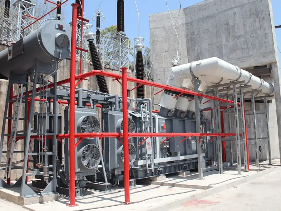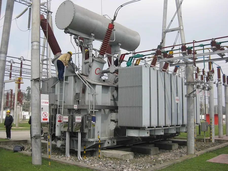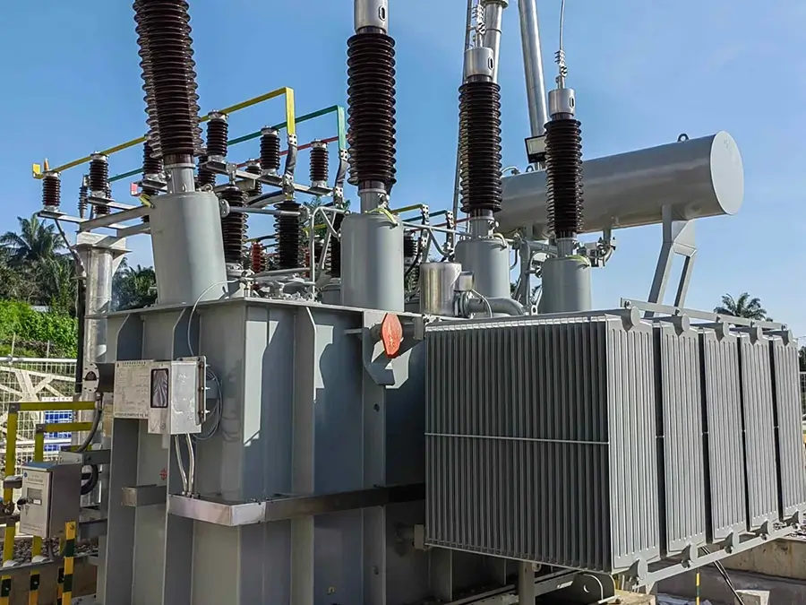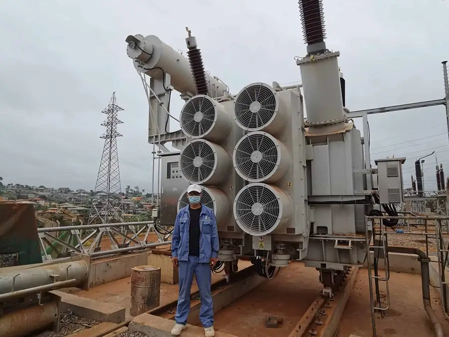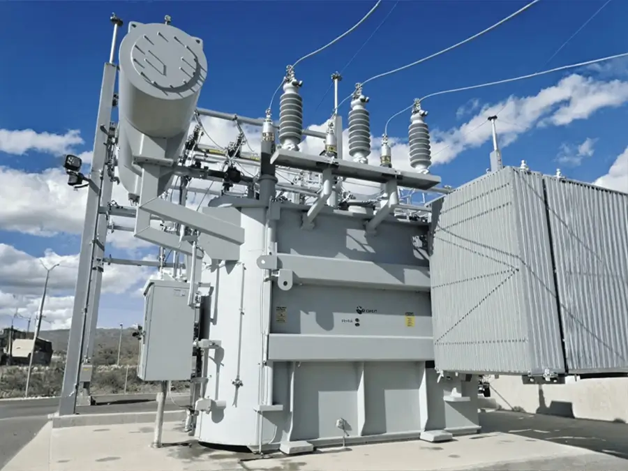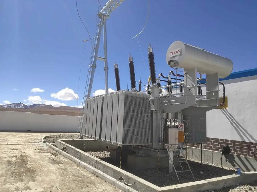






35kv three-phase oil-immersed rectifier power transformer
Overview
A rectifier transformer is a special power transformer dedicated to rectifier systems, widely used in industrial production and other fields. The working principle of a rectifier transformer is the same as that of an ordinary transformer. Based on the law of electromagnetic induction, it converts the AC voltage on the primary side (grid side) into the AC voltage on the secondary side (valve side), and then converts the AC power output from the valve side into DC power through rectifier components.
Brief Introduction
Ⅰ. Product Introduction
1.Executive Standards
International Standards: IEC 60076-1~5
2.Voltage Levels
①High-voltage side: Ranging from 0.4kV to 35kV ( 10kV, 20kV, 35kV). For extra-large rectifier transformers used in electrolysis, the voltage can reach 110kV~220kV.
②Low-voltage side: Depending on application scenarios, the common range is 600V~1500V (in the electrolysis industry), and in the electrostatic precipitator field, the DC voltage can reach 60kV~90kV.
3.Voltage Regulation Methods
On-load voltage regulation: Realizes stepless regulation through a 35-level continuous fine-coarse voltage regulating switch, suitable for scenarios requiring frequent voltage regulation ( electrolytic aluminum production).
4.Off-circuit voltage regulation: Manual adjustment via a tap changer, suitable for fixed load requirements ( urban rail transit).
5.High-voltage Tap Range
①Conventional range: ±2×2.5% (a total of 5 taps), applicable to scenarios where the grid voltage fluctuates by ±5%.
②Special design: Some transformers for electrolysis can be extended to ±10% to meet the needs of extreme voltage fluctuations.
6.Rated Capacity
①Small capacity: 30kVA~2500kVA (used in electroplating, electrical machining fields).
②Large capacity: 16000kVA~180000kVA (specialized products for electrolytic aluminum from enterprises such as TBEA).
7.Frequency: 50Hz or 60Hz
8.Phase Number
①Three-phase: Mainstream configuration, suitable for high-power industrial applications ( electrolysis, traction).
②Single-phase: Used in low-power scenarios ( electrostatic precipitators, small electroplating equipment).
9.Connection Groups
①Common types: Dyn11 (strong harmonic suppression capability), Yyn0 (neutral point grounded), Dy5 (phase-shifted rectification).
②Special design: Multi-winding phase-shifted connection (±7.5° phase shift), which can form a 24-pulse rectifier system.
10.Impedance Voltage
①Conventional range: 5%~10% (adjusted according to applications). Transformers for electrolysis are usually designed with 7%~8% to limit short-circuit current.
②High-impedance design: In the electrostatic precipitator field, the impedance can reach more than 12%, replacing external reactors.
11.Cooling Methods
Natural oil circulation (ON): Suitable for small-capacity transformers.
Forced oil circulation (OF): Equipped with radiators, used for large-capacity transformers.
12.Oil-immersed type:
①Dry type: Epoxy casting or NOMEX paper insulation, with AN/AF (natural air cooling/forced air cooling) and IP20~IP54 protection levels.
②Water cooling: Direct water-cooled windings, suitable for high-power density scenarios (e.g., high-voltage frequency converters).
13.Protection Levels
①IP20: For indoor use, protecting against solid foreign objects larger than 12mm.
②IP54: For outdoor or dusty environments, dust-proof and splash-proof ( in the metallurgical industry).
14.Insulation Classes
①Class F: Heat resistance up to 155℃, temperature rise ≤100K, the mainstream choice for epoxy-cast dry-type transformers.
②Class H: Heat resistance up to 180℃, NOMEX paper insulation, suitable for high-temperature environments ( petrochemical industry).
③Class B: Heat resistance up to 130℃, commonly used in traditional oil-immersed transformers.
Ⅱ. Operating Conditions
1.Altitude: ≤1000m (correction in accordance with GB3859 is required if exceeding this altitude).
2.Ambient Temperature: -25℃~+40℃, humidity ≤90% (no condensation).
3.Installation Method: Indoor/outdoor (with IP54 protection), and wall-mounted installation is supported (for dry-type structures).
Ⅲ. Test Types
1.Type Tests: Including temperature rise test (AN/AF mode), short-circuit withstand capability test (1.5 times rated current for 5 seconds).
2.Factory Tests: Insulation resistance test (using a 2500V megohmmeter), winding DC resistance measurement (deviation ≤±2%).
3.Special Tests: 72-hour salt spray test (for coastal areas), partial discharge measurement (≤50pC).
Ⅳ. Component Inspection
1.Key Components:
2.Windings: Eddy current loss analysis, interlayer insulation strength test.
3.Cooling System: Flow test (for forced oil circulation), fan performance verification.
4.Raw Material Certification: Silicon steel sheets must provide UL certification, and epoxy resin must comply with the IEC 60455 standard.
Ⅴ. Certification Types
International Certifications: CE (EU), UL (North America), TUV (Germany), CSA (Canada).
Structural Features
Ⅰ. Product Features
1.Reliable Insulation: A reasonable and reliable insulation level is determined based on load characteristics, grid voltage fluctuations, and other factors.
2.Insulation Model: The product’s environmental safety factor is ≥1.67, which can fully ensure the stability of electrical performance.
3.High Dynamic Stability: The windings have high mechanical strength. During the design and manufacturing process, dynamic instability sources caused by leakage flux and other factors are eliminated, enabling the transformer to meet the requirements of harsh load environments.
4.Strong Short-circuit Resistance: Special structural design and manufacturing processes are adopted, such as winding high-strength tight belts around the outer surface of the windings, giving it good short-circuit resistance and the ability to withstand the impact of short-circuit current.
5.Good Thermal Stability: With advanced product design, the heating parts and hot-spot temperature rise are strictly controlled. Copper conductors are used for coils and leads, and the current density is set low. The main temperature rise indicators are at least 5℃ lower than the national standard.
6.Strong Overload Capacity: It can operate safely for a long time under rated load, and can also operate safely with full load under 110% overvoltage for a long time. The terminals of the transformer connected to the motor can withstand 1.5 times the rated current for 5 seconds.
7.Flexible Voltage Regulation: Based on principles such as phase-controlled voltage regulation, self-saturating reactors or thyristors can be used to adjust the output voltage of the transformer, realizing stepless voltage regulation to meet the voltage requirements of different loads.
8.High Efficiency: Low-loss design is adopted, such as selecting high-magnetic-conductivity silicon steel sheets and optimizing the winding structure. The full-load efficiency is ≥98.5%, meeting the first-level energy efficiency standard and achieving significant energy-saving effects.
9.Compact Structure: Epoxy resin vacuum casting or open structure design is adopted, reducing the volume by 40% compared with traditional oil-immersed transformers. It supports wall-mounted installation, saving installation space.
10.Low Noise: High-quality materials and advanced manufacturing processes are used, such as special dipping processes and reasonable iron core lamination methods, effectively reducing vibration and noise during operation. The noise is usually<65dB.
11.Good Environmental Performance: Some rectifier transformers adopt a dry-type structure, which has the characteristics of heat resistance and moisture resistance, does not produce toxic gases, and is environmentally friendly. Moreover, the protection level can be selected to adapt to different usage environments.
Ⅱ. Product Advantages
1.Rectifier transformers are key equipment for realizing AC-to-DC conversion in power electronic systems. Their design and performance directly affect the stability, efficiency, and safety of rectifier systems. The following is a detailed analysis of the product advantages of rectifier transformers from multiple dimensions:
①Flexible Winding Design
The primary side (AC input) and secondary side (connected to the rectifier) windings of rectifier transformers can be designed with different turns ratios and wiring methods ( star, delta, zigzag) according to the type of rectifier circuit ( single-phase half-wave, full-wave, three-phase bridge), ensuring matching with the electrical parameters of rectifier components (diodes, thyristors, etc.), and reducing circuit losses and interference.
②Multi-winding Output Capability
Multiple sets of secondary windings can be designed to meet the needs of multiple sets of rectifier circuits working simultaneously ( scenarios requiring multiple sets of DC power supplies in industrial electrolysis and electroplating equipment), simplifying system wiring and improving space utilization.
③Leakage reactance can limit the amplitude of harmonic currents
Multiple rectifier transformers are combined with different phase-shifting angles, which can make harmonics cancel each other out and significantly reduce the total harmonic distortion rate.
④Improving Power Factor
A reasonably designed rectifier transformer can be combined with a filter device to improve the inductive load characteristics of the rectifier system, reduce reactive power loss, increase the power factor on the power grid side, and lower electricity costs.
⑤Adaptation to Overcurrent and Overvoltage Protection
Overcurrent protection windings can be integrated into the winding design or combined with relay protection devices. When overload or short-circuit occurs in the rectifier circuit, the power supply can be quickly cut off or the fault current can be limited, reducing the risk of equipment damage.
Product structure
Ⅰ. Production Process
1.The production process of rectifier transformers is a core link to ensure their adaptation to nonlinear rectifier loads, suppression of harmonic interference, and guarantee of long-term stable operation. It covers the entire process of precision control from raw material selection to finished product testing. The following is a detailed description of its main production processes:
①Silicon Steel Sheet Cutting:
CNC transverse shearing lines are used for precise cutting to ensure the sheet size deviation is ≤±0.1mm and the cutting burr is ≤0.02mm (to avoid increased eddy current loss).
②Iron Core Lamination:
The “non-laminated upper yoke” process is adopted (first laminating the iron core column, then inserting the upper yoke) to reduce lamination stress; the lamination factor is controlled between 0.96~0.97 (to improve magnetic conductivity).Insulating screws or binding tapes are used for fastening, with uniform fastening force (axial compression ≤1%) to avoid iron core vibration noise (no-load noise ≤65dB).
③Iron Core Grounding Treatment:
Single-point grounding (a grounding plate is led out from the bottom of the iron core) to prevent caused by multi-point grounding; the grounding resistance is ≤1Ω.
④Iron Core Manufacturing Process:
The iron core is the core of the magnetic circuit, and the process focuses on reducing iron loss, minimizing noise, and ensuring structural strength.
⑤Winding Manufacturing Process:
The winding is the core of the circuit and needs to meet the requirements of voltage resistance, short-circuit resistance, low loss, and harmonic adaptation:Dry-type transformers: The windings are cast with epoxy resin (vacuum degassing ≤-0.095MPa, curing temperature 130℃×8h) to ensure no bubbles in the insulation layer (bubble diameter ≤0.5mm).Oil-immersed transformers: The windings undergo pre-drying (105℃×48h, vacuum degree ≤10Pa), and after dipping in paint, they are dried (120℃×24h) to improve the integrity of the insulation.
⑥Coil Design and Winding:
According to the phase-shifted rectification requirements (e.g., 12/24 pulses), multi-winding segmented winding is adopted to ensure the phase difference accuracy of each winding is ≤±0.5°.The low-voltage winding (rectifier side) is wound using the foil method (copper foil thickness 0.3~0.5mm) to improve heat dissipation efficiency; the high-voltage winding is wound using the continuous or method to enhance insulation strength.
Specification
High and Low Voltage Three-Phase Oil-Immersed Electrical Power Transformer
| Rated Capacity | H.V. | L.V. | Connection Symbol | No-load loss(kw) | On-load loss(kw) | Short circuit impedance | ||
|---|---|---|---|---|---|---|---|---|
| S11 | S13 | S11 | S13 | S11 | ||||
| 50 | 35 38.5 |
0.4 | Dyn11 Yyn0 |
0.16 | 0.112 | 1.20/1.14 | 1.20/1.14 | 6.5 |
| 100 | 0.23 | 0.161 | 2.01/1.91 | 2.01/1.91 | ||||
| 125 | 0.27 | 0.189 | 2.37/2.26 | 2.37/2.26 | ||||
| 160 | 0.28 | 0.196 | 2.82/2.68 | 2.82/2.68 | ||||
| 200 | 0.34 | 0.238 | 3.32/3.16 | 3.32/3.16 | ||||
| 250 | 0.4 | 0.28 | 3.95/3.76 | 3.95/3.76 | ||||
| 315 | 0.48 | 0.336 | 4.75/4.53 | 4.75/4.53 | ||||
| 400 | 0.58 | 0.406 | 5.74/5.47 | 5.74/5.47 | ||||
| 500 | 0.68 | 0.476 | 6.91/6.58 | 6.91/6.58 | ||||
| 630 | 0.83 | 0.581 | 7.86 | 7.86 | ||||
| 800 | 0.98 | 0.686 | 9.4 | 9.4 | ||||
| 1000 | 1.15 | 0.805 | 11.5 | 11.5 | ||||
| 1250 | 1.4 | 0.98 | 13.9 | 13.9 | ||||
| 1600 | 1.69 | 1.183 | 16.6 | 16.6 | ||||
| 2000 | 1.99 | 1.393 | 19.7 | 19.7 | ||||
| 2500 | 2.36 | 1.652 | 23.2 | 23.2 | ||||
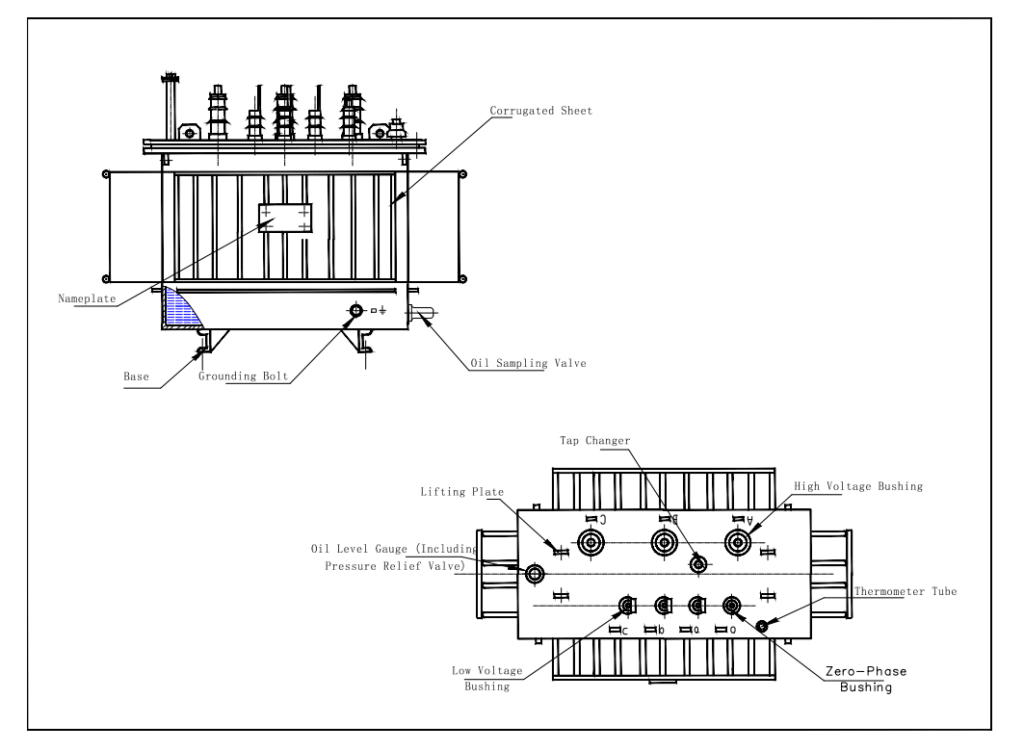
FAQ
1.What is a rectifier transformer? What is the difference between it and an ordinary power transformer?
A rectifier transformer is a special transformer dedicated to powering rectifier systems. Its core function is to convert the AC power from the power grid into AC power with a suitable voltage required by rectifiers (e.g., thyristors, diodes), and then the rectifiers output DC power.
2.How to calculate and select the capacity of a rectifier transformer?
① The selection of the capacity of a rectifier transformer is crucial, and the calculation formula is:
P = K × Ud × Id / η (kVA)
3.The rectifier transformer has an excessively high temperature rise during operation, even feeling hot to the touch. What is the reason?
①Harmonic currents: A large number of harmonic currents generated by rectifier loads lead to increased additional copper loss and iron loss, which is the most important reason.
②Overload operation: The actual load current exceeds the rated value for a long time.
③Cooling system failure: For example, the forced air cooling fan of an oil-immersed transformer stops running, the radiator is dirty and blocked, or the pipeline is blocked; the air duct of a dry-type transformer is blocked or the ambient ventilation is poor.
④Internal faults: Such as inter-turn short circuits in windings, multi-point grounding of the iron core leading to local overheating.
⑤Poor contact: The contact resistance at the connection points of the winding leads or bushings is too large, causing heat generation.
4.The rectifier transformer makes a lot of noise during operation. Is this normal?
The operating noise of a rectifier transformer is usually slightly higher than that of a power transformer, but abnormally loud noise is usually abnormal. Possible reasons include:
①Iron core issues: Loose iron core clamps, uncompressed silicon steel sheets, resulting in resonance under the action of a magnetic field.
②DC bias magnetization: Due to asymmetric triggering of the rectifier device or geomagnetic storms, DC components flow into the iron core, causing half-cycle saturation of the iron core, intensifying magnetostriction, and drastically increasing noise.
③Load harmonics: Harmonic magnetic fields cause vibration of components such as the shell and clamps.
④Winding issues: The windings become loose under the action of electric power.
5.What should I do if the output voltage of the rectifier transformer is unstable?
Voltage fluctuations at the output of a rectifier transformer are usually not a problem with the transformer itself. The following checks should be conducted first:
①Grid voltage: Check whether the voltage of the upper-level power grid is stable.
②Rectifier device: Check whether the trigger control system of the rectifier (e.g., thyristor) is normal, and whether the pulses are symmetrical and stable.
③Load changes: Check whether the DC load is fluctuating drastically.
④Tap changer: Check whether the gear position of the off-circuit tap changer is loose or displaced.
⑤Connection points: Check whether all primary and secondary electrical connection points are loose or oxidized.
6.What is a "phase-shifted rectifier transformer"? Why is it needed?
A phase-shifted rectifier transformer is a special rectifier transformer that generates multiple sets of secondary voltages with different phases through phase-shifted windings (e.g., extended delta connection). Its core purpose is to realize multi-pulse rectification (e.g., 12-pulse, 24-pulse, 36-pulse). Each additional set of phase shifts can cancel out specific orders of harmonics. The main benefits are: greatly reducing the harmonic current injected into the power grid to meet power quality requirements, reducing the ripple of the rectified output voltage to improve the power quality on the DC side, and increasing the system efficiency and capacity.
7.The oil-immersed rectifier transformer is leaking oil. How to handle this?
① Oil leakage needs to be handled in a timely manner: Report it immediately and take safety isolation measures.
② Find the leak point: Common leak points include welds, sealing gaskets (e.g., at bushings, valves, flanges), butterfly valves, and radiating pipes.
③ Temporary treatment: For slight oil seepage, clean the surface and use special leak-stopping glue for temporary sealing.
④ Professional maintenance: For severe oil leakage caused by weld cracks or the need to replace seals, professional personnel must perform welding repair or seal replacement after power failure and oil drainage. Live operation is strictly prohibited.
⑤ Replenish oil: After the treatment is completed, vacuumize and replenish new transformer oil of the same brand and with qualified test results to the specified oil level.
Why Choose us ?
Built to last, engineered to perform.
Kete Transformer is a key national-level manufacturer specializing in transformers, recognized as a “Contract-Honoring and Promise-Keeping” enterprise, a high-tech enterprise, and a national-level enterprise technology center. It is recommended in the national directory for rural and urban power grid construction and renovation, as well as a recommended supplier of major electromechanical equipment for hydropower projects. Its products have been awarded the title of “National Quality Inspection Qualified Product – Quality Trustworthy Product” and “Nationally Recognized Product for Mechanical Industry Users.
Our Project
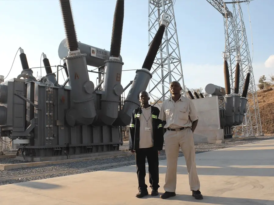
Our products not only dominate the domestic market but are also exported to more than 30 countries and regions, including Russia, Southeast Asia, Africa, and the Americas, serving industries such as power, municipal engineering, metallurgy, and petrochemicals.