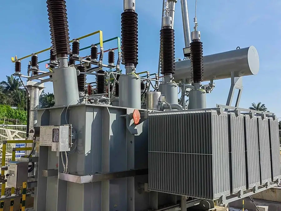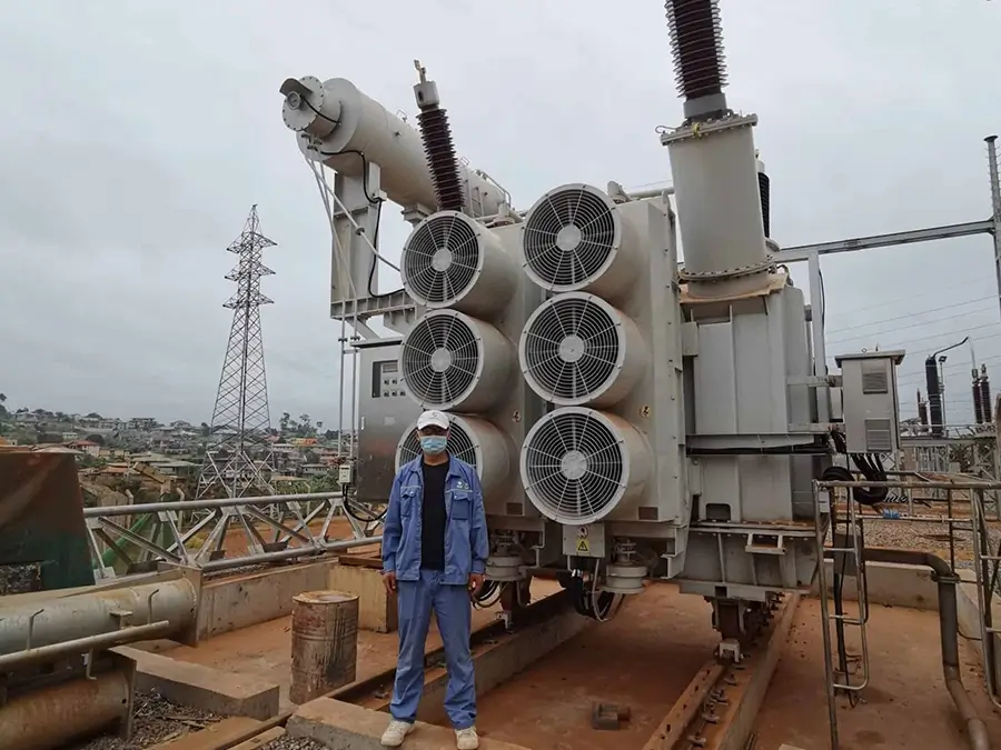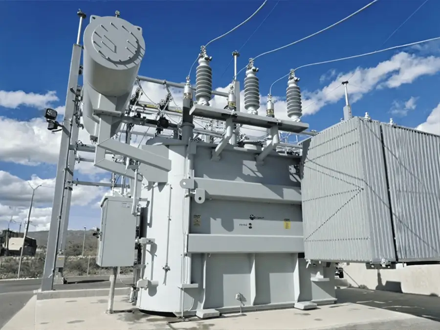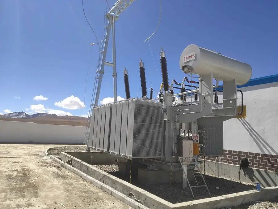






10kV S13/S20/S22-MRL 3D Wound Core Distribution Transformer
Overview
The oil-immersed three-dimensional wound core transformer is an energy-efficient power transformer. It adopts a three-dimensional wound core structure and uses oil as the cooling and insulating medium.
Brief introduction
Ⅰ.Brief introduction
1.Standards: IEC 60076, GB/T 1094, GB/T 25446-2010
2.Power Rating: 30KVA-2500 kVA
3.Primary Voltage: 6-11KV
4.Secondary Voltage: 0.4 kV or as required
5.Voltage regulation mode: off-circuit tap changing
6.Frequency: 50HZ or 60HZ
7.Type: 3 Phase Electric Power Transformer
8.Connection Type: Dyn11, Yyn0, or per client specification
9.insulation grade:A
10.Cooling method: ONAN
Ⅱ.Working conditions
1.Ambient Temperature: No more than +40℃ No less than -25℃, The monthly average temperature is no more than +30℃, The yearly average temperature is no more than +20℃
2.Altitude: No more than 1000m.
3.Relative air humidity:≤90%
4.installation site: no corrosion gas, No obvious dirt
5.Scope of application: Multiple fields such as power transmission and distribution in power systems, new energy power generation, self-use in industrial enterprises, and infrastructure construction.
Ⅲ.The tests for three-dimensional wound core transformer
The test types of oil-immersed three-dimensional wound core transformers can be divided into three categories: factory tests, type tests, and special tests.
1.Factory Tests (Mandatory for each product)
①Measurement of insulation resistance
②Measurement of winding DC resistance
③Measurement of voltage ratio and verification of connection group
④No-load test
⑤Short-circuit test
⑥Applied voltage withstand test (power frequency voltage withstand test)
⑦Induced voltage withstand test
⑧Sealing test
2.Type Tests (Mandatory for new products or after design changes)
Type tests include all contents of factory tests to ensure that basic performance meets the standards.
①Temperature rise test
②Lightning impulse voltage withstand test
③Switching impulse voltage withstand test (applicable to high-voltage transformers)
④Short-time short-circuit withstand capability test
⑤Measurement of no-load current harmonics
⑥Noise measurement
⑦Zero-sequence impedance measurement (for three-phase transformers)
3.Special Tests (Conducted according to user requirements or agreements)
①Partial discharge measurement
②Insulation thermal aging test
③Vibration measurement
④Test for multiple effects of short-circuit current
⑤Environmental adaptability test
Ⅳ.Component inspection of oil-immersed transformer
The component inspection contents of oil-immersed three-dimensional wound core transformers are as follows:
1.Inspection of Three-Dimensional Wound Core
①Measurement of insulation resistance
②Inspection of grounding reliability
③Evaluation of magnetic performance
④Inspection of structural integrity
2.Inspection of Windings
①Measurement of DC resistance
②Test of insulation resistance and absorption ratio
③AC withstand voltage test
④Detection of partial discharge
3.Inspection of Oil Tank and Structural Parts
①Inspection of appearance and tightness
②Monitoring of deformation
③Inspection of heat dissipation components
4.Inspection of Insulating Oil
①Breakdown voltage
②Moisture content
③Gas chromatography analysis
④Acid value and dielectric loss
5.Inspection of Tap Changer
①State of contacts
②Switching test
③Insulation inspection
6.Inspection of Bushings and Lead Wires
①Inspection of bushings
②Connection of lead wires
7.Inspection of Protection Devices
①Inspection of gas relay
②Inspection of temperature protection
③Inspection of pressure relief valve
Structural Features
Ⅰ.Product features
1.Iron Core
The iron core is made of cold-rolled silicon steel sheets with material performance not lower than 2a7ZH100, which are wound on a dedicated core winding machine using thin steel strips, ensuring uniform and tight pressure. It adopts a three-phase three-column stereoscopic symmetric structure in a triangular shape, eliminating the need for cutting or punching processes. This design eliminates the transverse and longitudinal seams of traditional iron cores, reducing magnetic resistance. The cross-section of the core column is circular, with a high filling factor.
2.Windings
Windings generally adopt corrugated oil channels and a non-painting process, and are bound with tightening belts, mostly using copper-core coils. The high-voltage winding is equipped with taps corresponding to the required tap voltage, which are led to the tap changer installed on the tank cover. The tap voltage can be adjusted after the power supply is cut off.
3.Oil Tank
The oil tank is usually composed of corrugated walls, with the surface treated by powder electrostatic spraying to ensure a firm paint film. The corrugated radiating fins not only have a cooling function but also can elastically compensate for the volume change of transformer oil caused by temperature rise and fall. Therefore, some fully sealed transformers do not have an oil conservator, which can reduce the overall height of the transformer.
Ⅱ.Product Advantages
Performance Advantages of Oil-Immersed Three-dimensional Wound Core Transformers
1.High Efficiency and Energy Saving: Adopting a three-phase wound core structure, the magnetic circuit is evenly distributed, which reduces the joint loss of traditional laminated cores. Both no-load loss and load loss are significantly reduced, and the energy efficiency level can reach S20 standard and above.
2.Low-Noise Operation: The three-dimensional wound core has fewer joints and lower magnetic resistance, which greatly reduces vibration and noise during operation. It is suitable for noise-sensitive environments such as residential areas, hospitals, and schools.
3.Excellent Heat Dissipation Performance: Mineral oil is used as the cooling medium, which provides excellent heat dissipation performance. It can effectively reduce the operating temperature of the transformer, making it suitable for long-term high-load operation and extending the service life of the equipment.
4.Strong Short-Circuit Resistance: Three-dimensional wound core has a stable structure and a reasonable winding design. Moreover, the core cross-section is mostly circular with good fastening effect, enabling it to withstand large short-circuit current impacts.
5.Compact Structure: The design of the three-dimensional wound core makes the transformer small in size and light in weight, facilitating transportation and installation. It can save space, making it particularly suitable for places with limited space.
Product structure
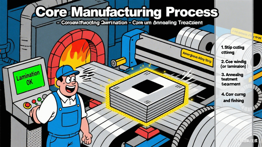
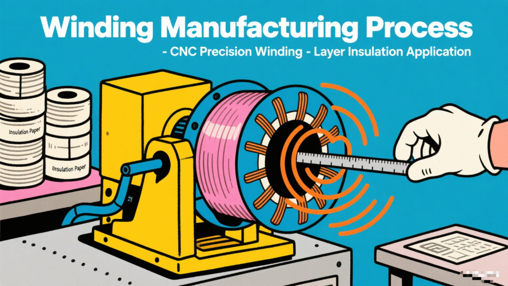
The core processes can be divided into five major stages: core component manufacturing, final assembly, insulation treatment, oil filling and vacuum treatment, and test detection. The specific procedures are as follows:
Ⅰ.Core Component Manufacturing
The core components of oil-immersed transformers include the iron core, windings, and oil tank. The manufacturing precision of these three components directly affects the performance of the transformer.
1.Iron Core Manufacturing
Cutting of silicon steel sheets, lamination and pressing, iron core drying, binding, and grounding.
2.Winding Manufacturing
Conductor processing, winding technology, pre-drying, and shaping.
3.Oil Tank and Accessory Manufacturing
Oil tank welding, heat dissipation structure processing, and accessory assembly.
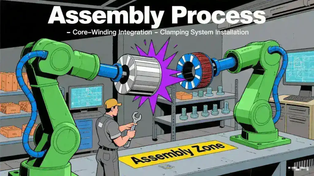
Ⅱ.Final Assembly
Assembling core components such as the iron core, windings, and insulators into an integrated transformer is a key step to ensure structural stability and insulation reliability, including core assembly, lead installation, overall fastening, and core drying.
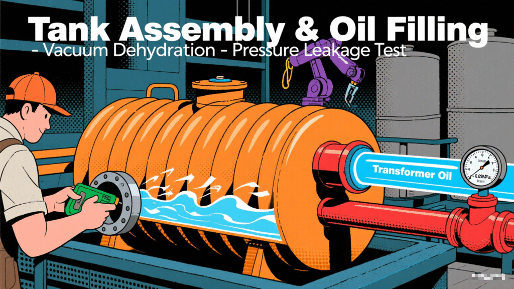
Ⅲ.Oil Filling and Vacuum Treatment
Insulating oil pre-treatment, filtration, vacuum dehydration and degassing, vacuum oil filling, and hot oil circulation.
Ⅳ.Overall Sealing and Appearance Treatment
1.Seal Testing: After oil filling, the transformer is left to stand for 24 hours. Tank welds and accessory interfaces are checked for leaks (using soapy water to detect bubbles). Leak points are repaired by welding or replacing seals.
2.Appearance Treatment: The tank surface is derusted, phosphatized, then painted with anti-rust paint and topcoat (outdoor products require weather-resistant coatings).
Ⅴ.Test Detection
After production, transformers must pass rigorous tests to ensure performance compliance, including routine tests, type tests, and special tests.

Specification
10kV S13/20/22-MRL 3D wound core transformer
| Rated Capacity | H.V. | L.V. | Connection symbol | No-load loss(w) | On-load loss(w) | Short circuit impedance | ||||
|---|---|---|---|---|---|---|---|---|---|---|
| S13 | S20 | S22 | S13 | S20 | S22 | |||||
| 30 | 6 6.3 10 10.5 11 |
0.4 | Dyn11 Yyn0 |
80 | 70 | 65 | 630/660 | 505/480 | 455/430 | 4 |
| 50 | 100 | 90 | 80 | 910/870 | 730/695 | 655/625 | ||||
| 63 | 110 | 100 | 90 | 1090/1040 | 870/830 | 785/745 | ||||
| 80 | 130 | 115 | 105 | 1310/1250 | 1050/1000 | 945/900 | ||||
| 100 | 150 | 135 | 120 | 1580/1500 | 1265/1200 | 1140/1080 | ||||
| 125 | 170 | 150 | 135 | 1890/1800 | 1510/1440 | 1360/1295 | ||||
| 160 | 200 | 180 | 160 | 2310/2200 | 1850/1760 | 1665/1585 | ||||
| 200 | 240 | 215 | 190 | 2730/2600 | 2185/2080 | 1970/1870 | ||||
| 250 | 290 | 260 | 230 | 3200/3050 | 2560/2440 | 2300/2195 | ||||
| 315 | 340 | 305 | 270 | 3830/3650 | 3065/2920 | 2760/2630 | ||||
| 400 | 410 | 370 | 330 | 4520/4300 | 3615/3440 | 3250/3095 | ||||
| 500 | 480 | 430 | 385 | 5410/5150 | 4330/4120 | 3900/3710 | ||||
| 630 | 570 | 510 | 460 | 6200 | 4960 | 4460 | 4.5 | |||
| 800 | 700 | 630 | 560 | 7500 | 6000 | 5400 | ||||
| 1000 | 830 | 745 | 665 | 10300 | 8240 | 7415 | ||||
| 1250 | 970 | 870 | 780 | 12000 | 9600 | 8640 | ||||
| 1600 | 1170 | 1050 | 940 | 14500 | 11600 | 10440 | ||||
| 2000 | 1360 | 1225 | 1085 | 18300 | 14640 | 13180 | 5 | |||
| 2500 | 1600 | 1440 | 1280 | 21200 | 14840 | 13360 | ||||
FAQs
Ⅰ.Basic Maintenance Service
1.What type of cooling system does the Kete oil-immersed 3D wound core transformer use?
Kete oil-immersed 3D wound core transformers mainly adopt two common cooling methods: ONAN and ONAF.
①Scope of Application of ONAN
·Transformers with small capacity
Typical applicable capacity: Usually used for transformers of 10kV class with 500kVA and below, and 35kV class with 1000kVA and below.
Reason: Small-capacity transformers have low losses (small heat generation), and natural heat dissipation can meet the temperature rise requirements, with a simple structure and low cost.
·Scenarios with loose installation environment
Suitable for outdoor open spaces, well-ventilated indoor distribution rooms, or areas with low ambient temperatures.
If installed in enclosed spaces (such as basements), additional evaluation of heat dissipation conditions is required, and the cooling method may need to be upgraded.
·Transformers with low load rate or intermittent operation
For transformers that are in a light load state for a long time (load rate < 50%), the heat dissipation capacity of ONAN is sufficient, without wasting energy consumption from forced cooling.
②Scope of Application of ONAF
·Medium and large capacity transformers
Typical applicable capacity: 10kV class with 800kVA and above, 35kV class with 1600kVA and above for small and medium-sized transformers.
Reason: Medium and large-capacity transformers have high losses (large copper loss and iron loss), and natural heat dissipation cannot meet the temperature rise limit, so fans are needed to assist in enhancing heat dissipation.
·Transformers with high load rate or continuous operation
Suitable for scenarios with long-term full-load operation or large load fluctuations (needing to cope with short-term overload), such as main transformers in industrial plants and hub transformers in urban distribution networks.
·Environments with limited heat dissipation conditions
If the transformer is installed in a poorly ventilated indoor environment or in areas with high ambient temperatures (such as tropical regions), ONAF can make up for the deficiency of natural heat dissipation through forced air cooling, avoiding excessive oil temperature that affects service life.
2.What is the main basis for choosing between ONAN and ONAF cooling methods for Kete oil-immersed 3D wound core transformers?
The choice between ONAN (Oil Natural Circulation and Air Natural Cooling) and ONAF (Oil Natural Circulation and Air Forced Cooling) cooling methods for Kete oil-immersed 3D wound core transformers is corely based on the matching between the transformer’s heat dissipation requirements and actual heat dissipation conditions. Specifically, it can be comprehensively judged from the following 5 key dimensions:
①Transformer Rated Capacity and Heat Generation from Losses
This is the most fundamental basis. The heat generated by a transformer mainly comes from copper losses (load losses) and iron losses (no-load losses). The larger the capacity, the higher the losses and the stronger the heat dissipation demand:
·Small-capacity transformers (low loss):
When the rated capacity is small (e.g., ≤500kVA for 10kV class, ≤1000kVA for 35kV class), the heat generated by losses is small. Heat can be dissipated through the natural convection of transformer oil (hot oil rises, cold oil falls) and the natural convection between the casing/radiator and air, without the need for additional cooling equipment. Therefore, ONAN is preferred.
·Medium and large-capacity transformers (high loss):
When the capacity exceeds the above range (e.g., ≥800kVA for 10kV class, ≥1600kVA for 35kV class), losses increase significantly, and the natural heat dissipation rate cannot match the heat generation. This may cause the oil temperature to exceed national standard limits (usually top oil temperature rise ≤55K or 60K). In such cases, fans must be used to force air flow and accelerate heat dissipation, so ONAF is chosen.
②Operating Load Characteristics
The actual load rate and operation mode of the transformer directly affect heat dissipation requirements:
·Low load rate or intermittent operation:
If the transformer operates at light load for a long time (load rate < 50%) or only runs during short-term peak periods (e.g., rural distribution transformers), even if its capacity is slightly larger, the actual heat generation is low. The natural heat dissipation capacity of ONAN can meet the demand, and there is no need to waste energy on fans. Thus, ONAN is selected.
·High load rate or continuous full-load operation:
For transformers in industrial parks, urban core distribution networks, and other equipment that operate at full load for a long time or have large load fluctuations (needing to cope with short-term overload), heat generation remains high. ONAN cannot meet the heat dissipation requirements, so ONAF’s forced air cooling via fans is necessary. Even during overload, fans can enhance heat dissipation capacity (usually supporting 10%-20% short-term overload). Hence, ONAF is chosen.
③Installation Environment and Heat Dissipation Conditions
Environmental factors directly affect the efficiency of natural heat dissipation, and cooling methods need to be adjusted according to scenarios:
·Well-ventilated and low-temperature environments:
If the transformer is installed in an open outdoor area, high-altitude regions (low air density but good ventilation), or cold areas, the efficiency of natural convection heat dissipation is high. Even if the capacity is close to the critical value, ONAN can be prioritized.
·Poorly ventilated and high-temperature environments:
If installed in enclosed distribution rooms, basements, tropical regions, or industrial environments with heavy dust/oil pollution, natural heat dissipation is hindered. Even with a slightly smaller capacity, oil temperature may rise excessively due to poor heat dissipation conditions. In such cases, upgrading to ONAF is necessary to compensate for environmental defects through forced air flow by fans.
④Cost and Maintenance Requirements
There are significant differences in initial costs and operation/maintenance costs between the two cooling methods:
·Advantages of ONAN:
It has no fans or control circuits, resulting in a simpler structure. The initial procurement cost is low (5%-10% lower than ONAF of the same capacity), and there is no need for motor maintenance, making long-term operation and maintenance costs almost zero. It is suitable for scenarios sensitive to cost and with limited maintenance resources (e.g., rural power grids, small user transformers).
·Disadvantages and necessity of ONAF:
It requires additional configuration of fans, thermostats, and power circuits, leading to higher initial costs. Fan motors need regular inspection (dust cleaning, bearing lubrication), involving certain maintenance workload and energy consumption (fan power is usually tens to hundreds of watts). However, for medium and large-capacity transformers or those with insufficient heat dissipation conditions, these costs must be borne to ensure safe operation. Thus, ONAF is a “necessary choice” rather than a “cost-priority choice.”
3.What are the advantages of Kete three-dimensional wound core transformers?
Compared with traditional laminated core transformers, the core advantages of three-dimensional (3D) wound core transformers can be summarized as “three lows and one high”, namely low loss, low noise, smaller size, and high reliability. The specific brief introduction is as follows:
①Stronger energy efficiency (low loss): The iron core is manufactured using a continuous winding process, resulting in a magnetic circuit with no seams. This eliminates the “hysteresis loss” and “eddy current loss” that occur in traditional laminated cores due to high magnetic resistance at the seams. As a result, the electrical energy conversion efficiency is higher, and long-term use can significantly reduce electricity costs.
②Quieter operation (low noise): The seamless structure avoids noise generated by the vibration of laminations. Additionally, the iron core has excellent overall tightness, leading to weaker electromagnetic vibration during operation. Typically, its noise level is 5-10 decibels lower than that of traditional transformers, making it more suitable for noise-sensitive scenarios such as residential areas and hospitals.
③Smaller size and lighter weight: For the same capacity, the transformer’s overall volume can be reduced by 15%-30% and its weight by 10%-20%, thanks to the low loss of the wound core and its more compact structure. This saves installation space (e.g., the floor area of distribution rooms) and lowers transportation and hoisting costs.
④Higher reliability: The magnetic flux density of the wound core is evenly distributed, preventing overheating caused by excessively high local magnetic flux density during long-term operation. Moreover, there is no issue of loose laminations, which reduces the risk of faults such as multi-point grounding of the iron core and short circuits, thus extending the service life.
Ⅱ.After-sales maintenance
1.What is included in Kete's warranty coverage during the warranty period? And how are the costs borne?
Our company’s warranty coverage includes performance failures caused by material defects or manufacturing process issues, such as cabinet water leakage, insulation failure, abnormal switch operation, etc.
We provide spare parts for maintenance free of charge, and will dispatch technical personnel for on-site inspection and repair if necessary, with travel expenses borne by the supplier.
2.Will Kete provide guidance documents for installation?
For large transformers that require the removal of some accessories to fit into containers, we will provide an installation video and an electronic version of the installation instructions.
3.If maintenance is required and spare parts are purchased from Kete, how long will it take for the spare parts to arrive?
If the customer needs to purchase spare parts from our company, the goods can generally be shipped within 2-7 days.
4.How to handle emergency maintenance requests, and what is the typical response time?
24/7 technical support hotline, ensuring a fault time of ≤ 2 hours.
5.What kind of after-sales support can Kete provide, including troubleshooting and maintenance services?
During the warranty period, regular return visits (once every 3 months) will be conducted to provide operation status testing and maintenance recommendations.
After the warranty period expires, lifelong maintenance services at cost price and spare parts supply can be provided.
6.Can Kete provide options for service contracts or extended warranty periods?
Yes, we can. Generally, the warranty period for our products is one year. If an extension of the warranty period is required, we will increase the price by a certain profit margin based on the existing price accordingly.
Ⅲ.Delivery and Payment
1.What is the manufacturing and delivery lead time for Kete oil-immersed transformers?
Generally speaking, if the customer provides detailed design drawings and specification requirements, transformers below 2500KVA can be completed within approximately 20 days; transformers above 2500KVA usually take about 30 to 40 days. The specific lead time depends on the complexity of the transformer.
2.What is the packaging for Kete oil-immersed transformers?
For LCL cargo, we will use wooden cases for packaging; for full containers, we will use wooden pallets to reinforce the packaging.
If you have legally registered patent, we can pack the goods in your branded boxes after getting your authorization letters.
3.What are the payment terms for Kete transformers?
①T/T 30% as deposit, and 70% before delivery.
②LC at sight
③DP at sight
4.What are the delivery terms for the bulk shipment of Kete transformers?
EXW, FOB, CFR, CIF or some other delivery terms inquired by customers.
Ⅳ.Systems and Certifications
1.Does the design of Kete oil-immersed transformers comply with specific industry standards and certifications?
Kete Oil-Immersed Transformers Meet Various International Standards, National Standards, and Core Certification Systems
①General Standards: IEC 60076, GB 1094
②Key Certification Systems
·Chinese Certifications: CCC Certification, ISO System Certification
·EU Certification: CE Certification
·US Certification: UL Certification
·Canadian Certification: GSA Certification
·Russian Certification: Gost Certification
·African Certification: COC Certification
Why Choose us ?
Built to last, engineered to perform.
Kete Transformer is a key national-level manufacturer specializing in transformers, recognized as a “Contract-Honoring and Promise-Keeping” enterprise, a high-tech enterprise, and a national-level enterprise technology center. It is recommended in the national directory for rural and urban power grid construction and renovation, as well as a recommended supplier of major electromechanical equipment for hydropower projects. Its products have been awarded the title of “National Quality Inspection Qualified Product – Quality Trustworthy Product” and “Nationally Recognized Product for Mechanical Industry Users.
Our Project
Our products not only dominate the domestic market but are also exported to more than 30 countries and regions, including Russia, Southeast Asia, Africa, and the Americas, serving industries such as power, municipal engineering, metallurgy, and petrochemicals.