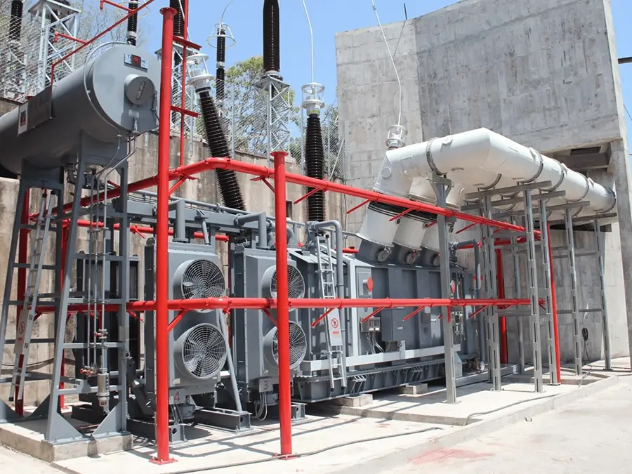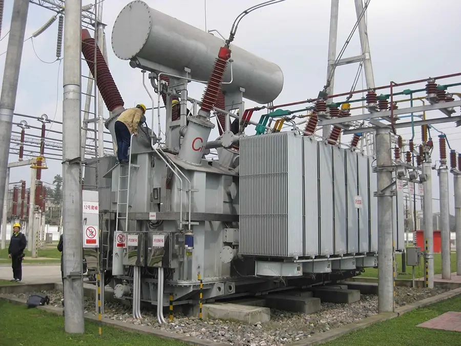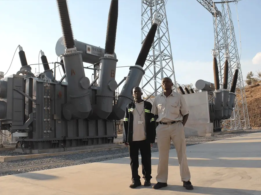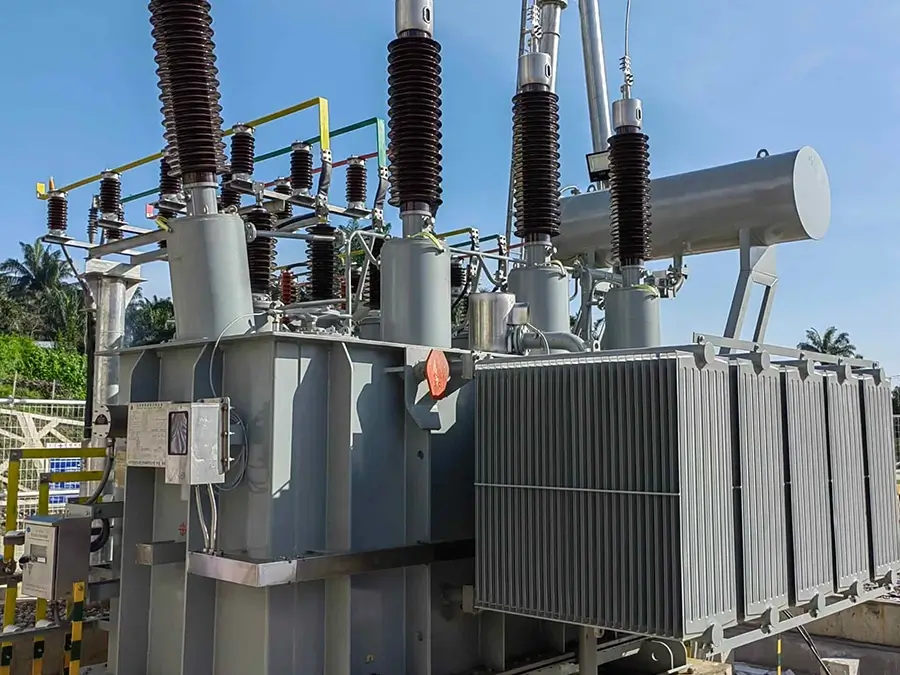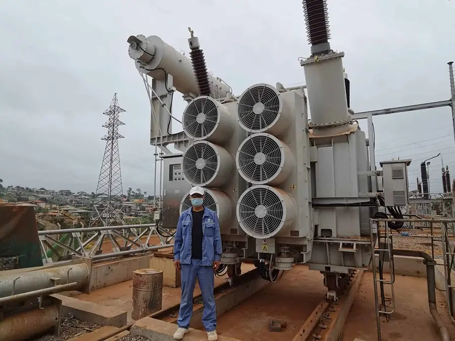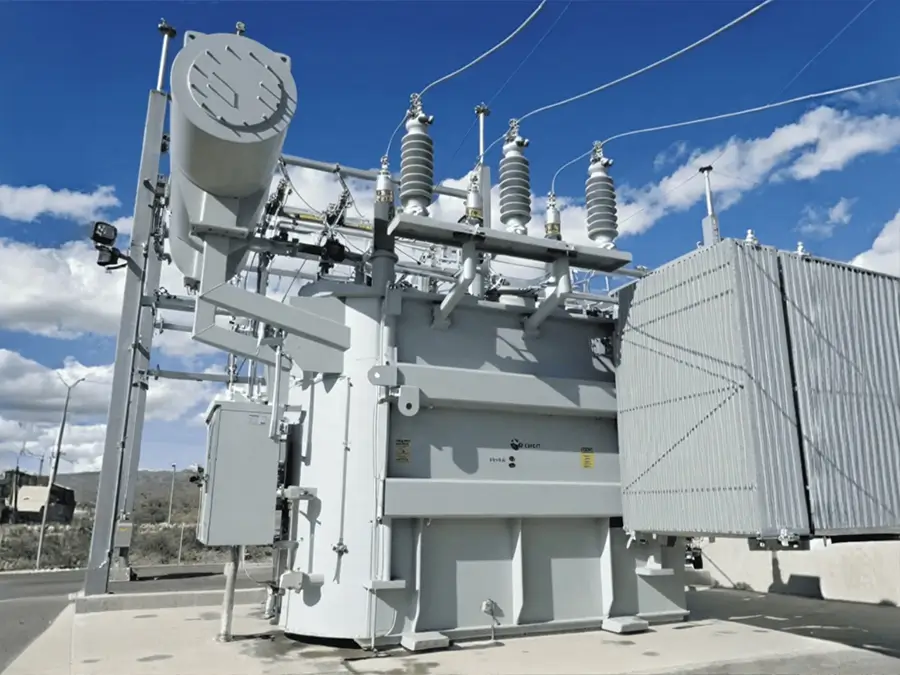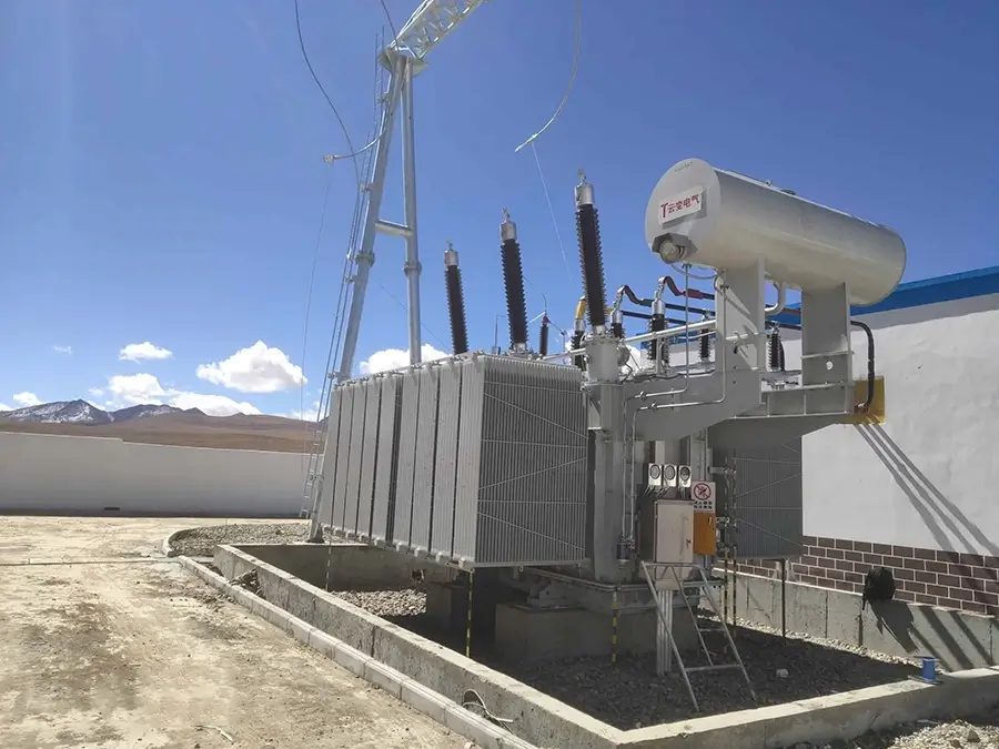






10kv 2000KVA three-phase oil-immersed photovoltaic distribution power transformer
Overview
A photovoltaic transformer is a core device in a photovoltaic power generation system that realizes voltage conversion and electric energy transmission. Its main task is to step up the electric energy generated by PV modules (usually at a relatively low voltage) to a higher voltage level suitable for grid connection or long-distance transmission. As the “voltage regulator” and “power gateway” of a PV power station, the performance of the PV transformer is directly related to the power generation efficiency, operational stability, and investment return of the station.
Brief Introduction
Ⅰ. Product Introduction
1.Executive Standards
transformers must comply with multiple core standards at home and abroad:
Standards: IEC 60076 (International Standard for Power Transformers), UL 1561 (Certification for Dry-Type Transformers in North America), EN 50438 (European Standard for PV Systems).
2.Voltage Level
①Input Voltage: Commonly 3-phase 800V, 690V (for distributed PV systems); for large-scale power stations, it can reach 35kV, 110kV.
②Output Voltage:
Low-voltage side: 400V, 380V (for grid connection or load power supply).
High-voltage side: 35kV (for box-type step-up transformers), 110kV (for main transformers).
Voltage Regulation Method
No-load voltage regulation
On-load voltage regulation
High-Voltage Tap Range
3.Conventional Range:
±5% ( ±2×2.5% for 10kV transformers).
±10% ( ±8×1.25% for 35kV main transformers).
4.Distributed Scenarios: 50kVA ~ 2500kVA
5.Centralized Power Stations: 1000kVA ~ 80000kVA (110kV step-up main transformers).
6.Combined Box-Type Transformers: Typical capacity ranges from 1000kVA to 2500kVA, supporting parallel operation of multiple units for capacity expansion.Frequency
7.The standard frequency is 50Hz or 60Hz.
8.Connection Group
①Dyn11: Neutral point grounding on the low-voltage side
②YNd11: Neutral point grounding on the high-voltage side
9.Impedance Voltage
①Low-voltage side: 4% ~ 6% (transformers converting 800V to 400V).
②High-voltage side: 10.5% ~ 14% ( 110kV main transformers).
10.Cooling Method
①Dry-Type Transformers:
Natural Air Cooling (AN): Suitable for indoor or low-load scenarios ( industrial and commercial rooftops).
Forced Air Cooling (AF): Enhances heat dissipation through fans and supports short-term overload ( Instand transformers).
②Oil-Immersed Transformers:
ONAN (Oil-Immersed Natural Cooling): The first choice for outdoor large-scale power stations ( ZGS-Z.G-1000 box-type transformers).
11.Protection Class
①Outdoor Scenarios: IP54 (dust and water protection) or IP65 (water spray protection)
②Indoor Scenarios: IP20 (basic protection), suitable for dust-free environments.
12.Insulation Class
①Class H Insulation (Temperature Resistance: 180℃): The mainstream choice for dry-type transformers.
②Class A Insulation (Temperature Resistance: 105℃): Commonly used in oil-immersed transformers for special environments; moisture-proof insulation materials are required in high-humidity areas.
Ⅱ. Operating Conditions
1.Ambient Temperature: -40℃ ~ +45℃ (alpine-type transformers can start at -50℃).
2.Altitude: Conventional models ≤1000m; high-altitude models (above 3000m) require enhanced insulation.
3.Humidity Requirement: Daily average humidity ≤95%, monthly average humidity ≤90%.
Ⅲ. Test Types
1.Type Tests
Temperature rise test, short-circuit withstand test, partial discharge test (in compliance with IEC 60076).
2.Routine Tests
Insulation resistance test, transformation ratio and polarity check, winding DC resistance measurement.
3.Special Tests
Lightning impulse test (1.2/50μs waveform), long-duration induced withstand voltage test (with partial discharge detection).
Ⅳ. Component Inspection
1.Winding Inspection
Frequency Response Analysis (FRA) is used to detect deformation and ensure short-circuit resistance.
2.Core Inspection
Measurement of no-load loss and excitation current to verify the quality of silicon steel sheets.
3.Bushing Inspection
Dielectric loss and capacitance tests to identify insulation defects.
Ⅴ. Certification Types
International Certifications
CE Certification (market access for Europe), UL Certification (North America), CSA Certification (Canada).
Structural Features
Ⅰ. Product Characteristics
Core Design for High Efficiency and Energy Saving
1.Material Innovation
Amorphous alloy cores ( amorphous three-dimensional transformers from Ankang Shaanbian) are adopted, reducing no-load loss by 60%-80% compared with traditional silicon steel sheets, with annual power savings up to 80,000 kWh (calculated based on 1000 hours of operation).Nano-crystalline alloy cores combined with stepped joint technology reduce hysteresis loss by 30%, achieving a conversion efficiency of up to 98.7%, far exceeding national standards.
2.Dynamic Energy Efficiency Optimization
The intelligent temperature control system automatically adjusts fan speed according to the load, reducing load loss by 15%.Nano-crystalline alloy cores maintain high efficiency even under low loads, adapting to the intermittent power generation characteristics of PV systems.Wide-Range Adaptability and Precise Regulation
3.Voltage Compatibility
The input range covers distributed voltages such as 690V and 800V, and the output supports low-voltage grid connection of 380V, 400V and high-voltage grid connection of 35kV, 110kV.Dynamic compensation technology controls voltage fluctuation within ±0.5%, improving stability by 60% compared with traditional equipment.
4.Wide-Frequency Operation
The standard frequency is 50/60Hz, supporting ±2% fluctuation; special designs can be compatible with wide-frequency operation of 45-65Hz, adapting to multi-energy complementary scenarios such as wind power and energy storage.High Reliability and Environmental Adaptability
5.Multi-Protection System
①Insulation and Protection: Class H insulation (temperature resistance: 180℃) combined with IP54/IP65 protection class enables stable operation in a wide temperature range of -40℃ ~ +55℃.
②Corrosion Resistance Design: Zinc-nickel alloy coating + fluorocarbon paint spraying (salt spray test ≥1500 hours), suitable for coastal high-salt-spray and desert high-dust environments.
③Short-Circuit and Vibration Resistance
Windings adopt pre-stressed carbon fiber binding technology, which can withstand a vibration acceleration of 5g. The short-circuit impedance is controlled at 4.5%, and the short-circuit withstand current reaches 20kA (for 4 seconds).
Ⅱ. Product Advantages
1.Harmonic Resistance and Power Quality Optimization
①Harmonic Suppression Technology
Dual shielding design (copper foil electrostatic shielding + magnetic shielding layer) and staggered winding layout are adopted to control the Total Harmonic Distortion (THD) within 1.8%-3%, far exceeding the standards of GB/T 14549 and IEEE 519.
2.DC Component Management
Cores are coated with nano-crystalline ribbons to suppress switching harmonics above 20kHz.Windings adopt VPI (Vacuum Pressure Impregnation) technology to enhance resistance to DC bias magnetization and avoid high-frequency noise interference from inverters.Modular and Scenario-Specific Design
3.Flexible Structural Configuration
①Dry-Type Transformers: Small size, maintenance-free, suitable for industrial and commercial rooftops ( Instand SG-50KVA).
②Oil-Immersed Transformers: Strong heat dissipation performance, suitable for 110kV large-scale power stations ( SZ11 main transformers).
③Combined Box-Type Transformers: Integrate transformers, switches, and protection devices, reducing the floor area by 30% and shortening the construction period to 3 days.
4.Customization for Special Scenarios
①High-Altitude Type: Enhanced insulation design, suitable for plateaus above 3000 meters.
②Alpine Type: Capable of starting at -50℃, equipped with an oil tank heating device.
③Agriculture-PV Complementary Type: Low noise (≤55dB), moisture-proof and anti-condensation, without affecting fish growth.
5.Safety and Environmental Certifications
①International Compliance: Certified by CE, UL, IEC 61378, etc., complying with the European VDE-AR-N 4105 low-voltage grid connection standard and the Chinese PCCC certification, ensuring global market access.
②Sustainable Design: Amorphous alloy materials are recyclable, reducing production loss by 20%; the modular design supports component replacement, reducing electronic waste generation. For example, after adopting Zhuoerfan transformers, an automobile factory reduces carbon dioxide emissions by 1200 tons annually, achieving green production.
6.Low Noise and Ecological Friendliness
①Quiet Operation: Optimized magnetic circuit design and cooling system control noise within 30-55dB, meeting the requirements of noise-sensitive scenarios such as residential areas and hospitals. For example, fishery-PV complementary transformers reduce noise below the threshold of aquaculture equipment through a honeycomb-shaped heat dissipation structure.
②Ecological Adaptability: The fire rating reaches UL94 V-0, and halogen-free insulation materials are used to avoid pollution to soil and water sources; the appearance design integrates with the surrounding environment, suitable for ecologically sensitive areas such as agriculture-PV complementary projects and tourist attractions.
Product structure
Ⅰ. Production Process
1.Core Material Selection Standards
①Core Materials: Amorphous alloys (Fe-Si-B series, thickness 0.02-0.03mm) or nano-crystalline alloys (nano-crystalline ribbons, saturation magnetic flux density ≥1.8T) are preferred, which must meet the requirement of no-load loss ≤0.1W/kg (50Hz); traditional silicon steel sheets use high-magnetic-induction oriented silicon steel such as 30Q130, with iron loss ≤1.3W/kg.
②Winding Conductors: High-purity oxygen-free copper wires (oxygen content ≤0.003%) or copper foils (thickness 0.5-3mm) are used, with electrical conductivity ≥98% IACS and tensile strength ≥300MPa; for special scenarios (e.g., high-corrosion environments), tinned copper wires or aluminum-magnesium alloy wires can be used (with supporting anti-corrosion treatment).
③Insulation Materials: Materials with temperature resistance ≥180℃ are selected according to the insulation class (Class H or Class C), such as Nomex paper, polyimide film, and epoxy glass cloth board, which must pass the UL94 V-0 fire certification and have UV resistance and anti-aging properties (no cracking after accelerated aging test ≥1000 hours).
2.Preprocessing Technology
①Conductor Preprocessing: Copper wires/foils are annealed in a continuous annealing furnace (temperature 400-500℃, nitrogen protection) to eliminate stress and improve ductility; the surface is phosphated (to form an oxide film) or tinned (thickness 5-10μm) to enhance adhesion to the insulation layer.
②Insulation Material Preprocessing: Insulation paper/film is vacuum-dried (80-100℃, vacuum degree ≤10Pa) to remove moisture (moisture content ≤0.5%); glass fiber cloth needs to be pre-impregnated with glue (epoxy resin content 30-40%) to ensure uniform curing in subsequent processes.
③Auxiliary Material Preprocessing: Aluminum profiles (radiators) used in the cooling system undergo anodization (film thickness ≥15μm) or fluorocarbon spraying (thickness 50-80μm), passing a salt spray test ≥1000 hours; oil tank steel plates (Q235B) are derusted by sandblasting (Sa2.5 level) to improve paint film adhesion.
3.Core Manufacturing Technology
The core is the magnetic circuit core of the PV transformer, and its technology directly affects no-load loss and noise. High-precision processing is required to achieve low loss and high magnetic permeability.
①Core Cutting: CNC laser cutting machines (precision ±0.05mm) or high-speed punch presses (punching speed ≥300 times/minute) are used to cut silicon steel sheets/amorphous ribbons into stepped or beveled sheets (bevel angle 45°) according to the design size, reducing magnetic leakage at the joints.
②Annealing Treatment: Silicon steel sheet cores undergo high-temperature annealing (750-800℃, nitrogen protection, heat preservation for 4-6 hours) to eliminate processing stress and improve magnetic flux density; amorphous alloy cores require low-temperature annealing (200-250℃, vacuum environment) to prevent crystallization failure.
4.Winding Manufacturing Technology
The winding is the core of current conversion, which needs to meet the requirements of high insulation, low loss, and short-circuit resistance. The technology focuses on winding precision and insulation reliability.
5.Insulation and Cooling System Integration Technology
①Oil-Immersed Transformers: After the core is placed in the oil tank, insulating oil (25# or 45# transformer oil) is injected, and vacuum degassing is performed (vacuum degree ≤1Pa, degassing time 8-12 hours), with moisture content ≤10ppm and dielectric loss factor (90℃) ≤0.005; the inner wall of the oil tank is coated with oil-resistant primer, and the outer wall is coated with sun-protective and anti-corrosion paint (thickness ≥80μm).
②Dry-Type Transformers: The surface of the core is sprayed with insulating protective paint (Class H, thickness 0.1-0.2mm), key parts (e.g., lead joints) are sealed with insulating casting compound, and the overall insulation resistance is ≥1000MΩ (25℃).
6.Intelligent Component Integration Technology
PV transformers need to support condition monitoring, and the integration of intelligent components must ensure accurate signals and anti-interference performance.
Specification
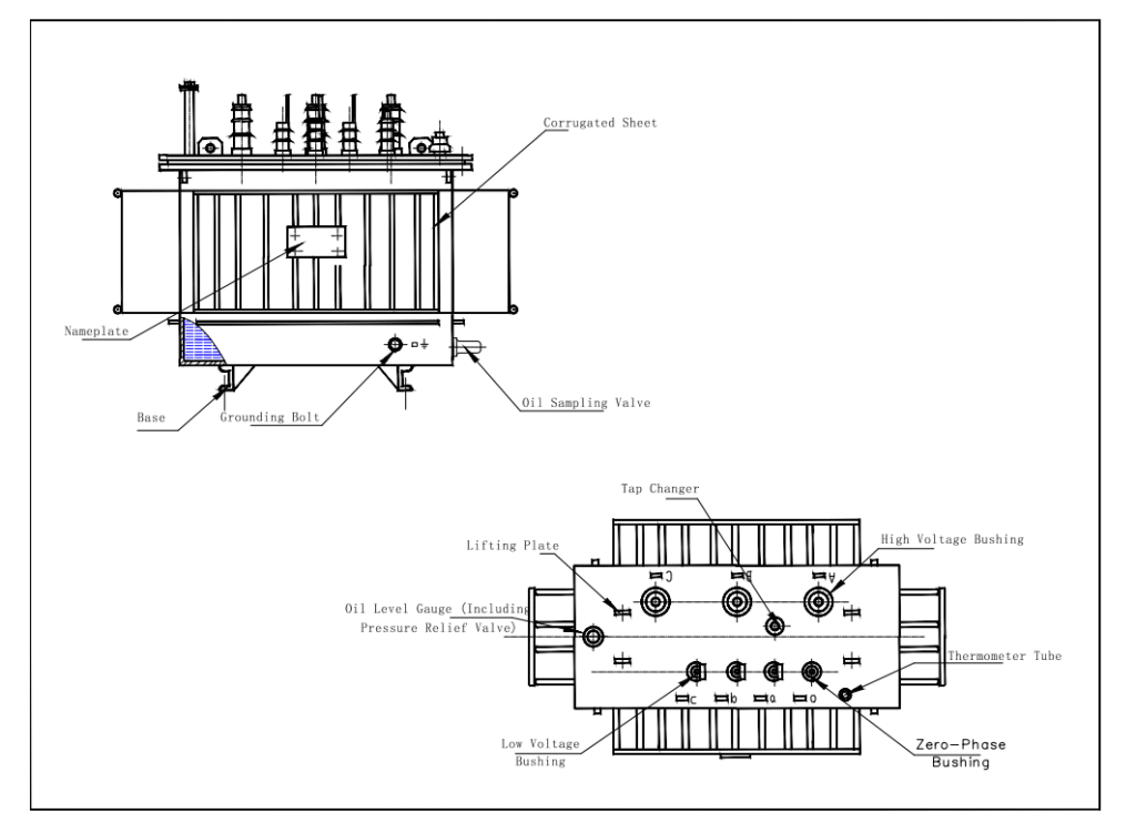
2000kVA Photovoltaic Power Generation 10kv Three Phase Oil Immersed Distribution Power Electrical Transformer
| Rated Capacity | H.V. | L.V. | Connection symbol | No-load loss(w) | On-load loss(w) | Short circuit impedance | ||||
|---|---|---|---|---|---|---|---|---|---|---|
| S13 | S20 | S22 | S13 | S20 | S22 | |||||
| 30 | 6 6.3 10 10.5 11 |
0.4 | Dyn11 Yyn0 |
80 | 70 | 65 | 630/660 | 505/480 | 455/430 | 4 |
| 50 | 100 | 90 | 80 | 910/870 | 730/695 | 655/625 | ||||
| 63 | 110 | 100 | 90 | 1090/1040 | 870/830 | 785/745 | ||||
| 80 | 130 | 115 | 105 | 1310/1250 | 1050/1000 | 945/900 | ||||
| 100 | 150 | 135 | 120 | 1580/1500 | 1265/1200 | 1140/1080 | ||||
| 125 | 170 | 150 | 135 | 1890/1800 | 1510/1440 | 1360/1295 | ||||
| 160 | 200 | 180 | 160 | 2310/2200 | 1850/1760 | 1665/1585 | ||||
| 200 | 240 | 215 | 190 | 2730/2600 | 2185/2080 | 1970/1870 | ||||
| 250 | 290 | 260 | 230 | 3200/3050 | 2560/2440 | 2300/2195 | ||||
| 315 | 340 | 305 | 270 | 3830/3650 | 3065/2920 | 2760/2630 | ||||
| 400 | 410 | 370 | 330 | 4520/4300 | 3615/3440 | 3250/3095 | ||||
| 500 | 480 | 430 | 385 | 5410/5150 | 4330/4120 | 3900/3710 | ||||
| 630 | 570 | 510 | 460 | 6200 | 4960 | 4460 | 4.5 | |||
| 800 | 700 | 630 | 560 | 7500 | 6000 | 5400 | ||||
| 1000 | 830 | 745 | 665 | 10300 | 8240 | 7415 | ||||
| 1250 | 970 | 870 | 780 | 12000 | 9600 | 8640 | ||||
| 1600 | 1170 | 1050 | 940 | 14500 | 11600 | 10440 | ||||
| 2000 | 1360 | 1225 | 1085 | 18300 | 14640 | 13180 | 5 | |||
| 2500 | 1600 | 1440 | 1280 | 21200 | 14840 | 13360 | ||||
FAQ
1.What is the working principle of a PV transformer?
PV transformers are mainly used in PV power generation systems to step up the low-voltage DC power generated by PV modules (after being converted to low-voltage AC power by an inverter) to a voltage level suitable for grid connection. It works based on the principle of electromagnetic induction: an AC current is passed through the primary winding to generate an alternating magnetic flux through a closed magnetic circuit formed by the core. This magnetic flux passes through the secondary winding, and an electromotive force is induced in the secondary winding according to Faraday’s law of electromagnetic induction, realizing voltage conversion. For example, a common 10kV PV step-up box-type transformer steps up the 0.4kV low-voltage AC power output by the inverter to 10kV for grid connection.
2.How to select a PV transformer with the appropriate capacity?
Selection should comprehensively consider the scale of the PV array, the capacity of the inverter, and the load characteristics during actual operation. First, clarify the maximum output power of the PV array. Usually, the rated power of the inverter matches the PV array, and the transformer capacity should be slightly larger than the rated output power of the inverter. For example, for a 500kW PV power station, the configured inverter may be 500kW, and a transformer with a capacity of 500-630kVA can be selected. At the same time, a certain margin should be considered to cope with power fluctuations caused by factors such as changes in sunlight, ensuring that the transformer can operate stably without overload under various working conditions.
3.What are the common faults of PV transformers and how to solve them?
① Insulation Faults: Long-term exposure to complex outdoor environments leads to erosion by moisture, dust, and pollutants, causing aging, cracking, or even breakdown of insulation materials, resulting in partial discharge and, in severe cases, short circuits or leakage.Solutions: Conduct regular professional insulation tests, install rain shields and dust screens to reduce external erosion, and replace aging insulation materials in a timely manner.
② Temperature Rise Faults: Heat is generated due to iron loss and copper loss during transformer operation. Unreasonable design of the cooling system or excessive load will cause abnormal temperature rise, accelerating insulation aging or even damaging the transformer.Solutions: Optimize the design of the cooling system, conduct regular temperature rise monitoring, install temperature sensors for real-time monitoring, adjust the operating load, and add cooling equipment if necessary.
4.What is the maintenance cycle of PV transformers?
① Daily Inspection: Check the working status of the PV transformer every day, including temperature, vibration, noise, etc., to detect abnormalities in a timely manner.
② Quarterly Inspection: Check the electrical and mechanical properties every quarter, such as output voltage, current, power factor, and whether the mechanical parts of the transformer are worn or loose.
③ Annual Overhaul: Conduct a comprehensive overhaul every year, including cleaning the internal and external surfaces of the equipment to remove impurities such as dust and oil; inspecting the internal components of the transformer, such as the status of the core, windings, and tap changers; replacing damaged parts; maintaining the cooling system, such as cleaning radiators and checking the operation of fans; and testing the insulation performance.
5.What to do if the temperature of the PV transformer is too high during operation?
First, determine the cause of the excessive temperature. If the load is too high, adjust the load in a timely manner by reasonably distributing the power generation of the power station and transferring part of the load to other transformers to avoid long-term overload operation. If the cooling system fails, for oil-immersed transformers, clean the dust and debris on the cooling fans and oil pumps, repair or replace damaged parts to ensure normal oil circulation cooling; for dry-type transformers, check whether the cooling fans are working normally, and repair or replace them if necessary. At the same time, improve the operating environment of the transformer to ensure good ventilation at the installation site. In high-temperature summers, measures such as shading and adding ventilation equipment can be taken to reduce the ambient temperature. If it is suspected that the insulation between the silicon steel sheets of the core is damaged, causing temperature rise, power off the transformer for maintenance and reapply insulating paint to restore insulation performance.
6.What are the causes of oil deterioration in PV transformers and the treatment methods?
①The main causes of oil deterioration are: oxidation reactions occur under the influence of temperature, oxygen, and electric fields during long-term operation; poor sealing of the transformer leads to moisture ingress, reducing insulation performance; metal debris generated by internal component wear and aging and falling off of insulation materials are mixed into the oil; excessive oil temperature accelerates oxidative aging.
②Treatment methods: Filter the deteriorated oil using a vacuum oil filter to remove impurities and moisture, improving the purity and insulation performance of the oil; if the oil is severely deteriorated, replace it with new oil and thoroughly clean the transformer oil tank when replacing; check the sealing condition of the transformer, repair leakage points, and replace aging gaskets to prevent moisture and impurities from entering again.
7.What causes abnormal noise from PV transformers?
① Loose Core: The core is composed of laminated silicon steel sheets. Loosening of the clamping bolts causes vibration between the silicon steel sheets, resulting in increased abnormal noise. Power off the transformer for maintenance and re-tighten the core clamping bolts.
② Winding Faults: Short circuits, open circuits, or insulation damage of the windings cause abnormal current and thus abnormal noise. Conduct insulation tests and DC resistance measurements to identify the fault location, then repair or replace the windings.
③ Poor Contact of Tap Changers: Poor contact of the contacts when switching tap changer gears leads to spark discharge and a “squeaking” sound. Try switching the gears multiple times to clean the oxide layer on the contact surface; if the problem cannot be solved, disassemble, inspect, or replace the tap changer.
④ Foreign Objects Inside the Transformer: Foreign objects such as metal debris and insects enter the transformer and vibrate under the action of the electromagnetic field, producing noise. Power off the transformer, open the oil tank, and clean the foreign objects.
Why Choose us ?
Built to last, engineered to perform.
Kete Transformer is a key national-level manufacturer specializing in transformers, recognized as a “Contract-Honoring and Promise-Keeping” enterprise, a high-tech enterprise, and a national-level enterprise technology center. It is recommended in the national directory for rural and urban power grid construction and renovation, as well as a recommended supplier of major electromechanical equipment for hydropower projects. Its products have been awarded the title of “National Quality Inspection Qualified Product – Quality Trustworthy Product” and “Nationally Recognized Product for Mechanical Industry Users.
Our Project
Our products not only dominate the domestic market but are also exported to more than 30 countries and regions, including Russia, Southeast Asia, Africa, and the Americas, serving industries such as power, municipal engineering, metallurgy, and petrochemicals.