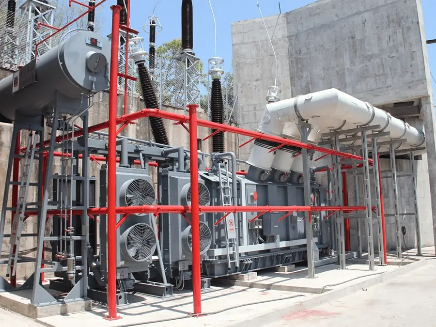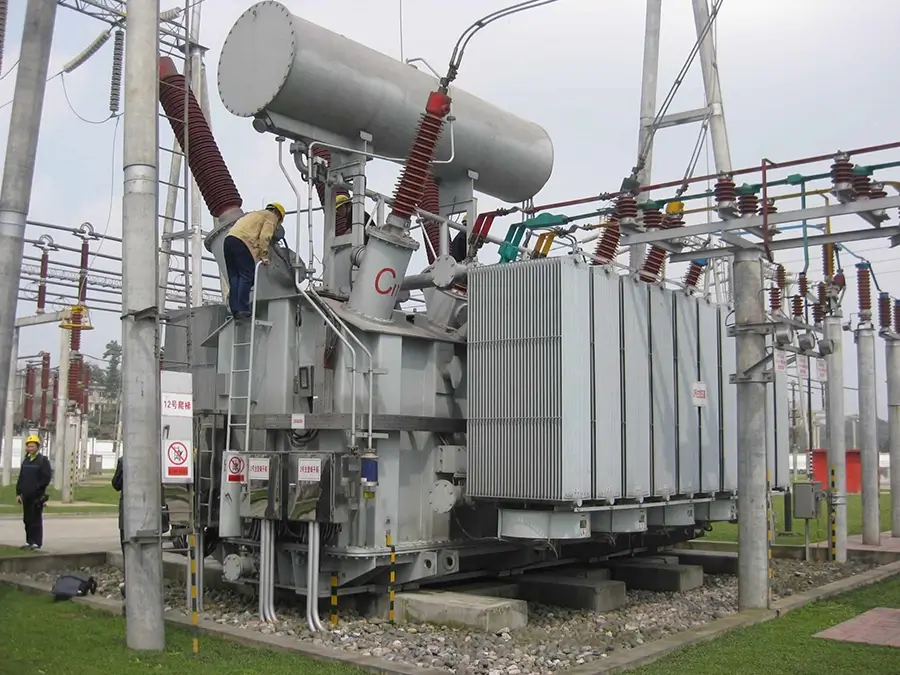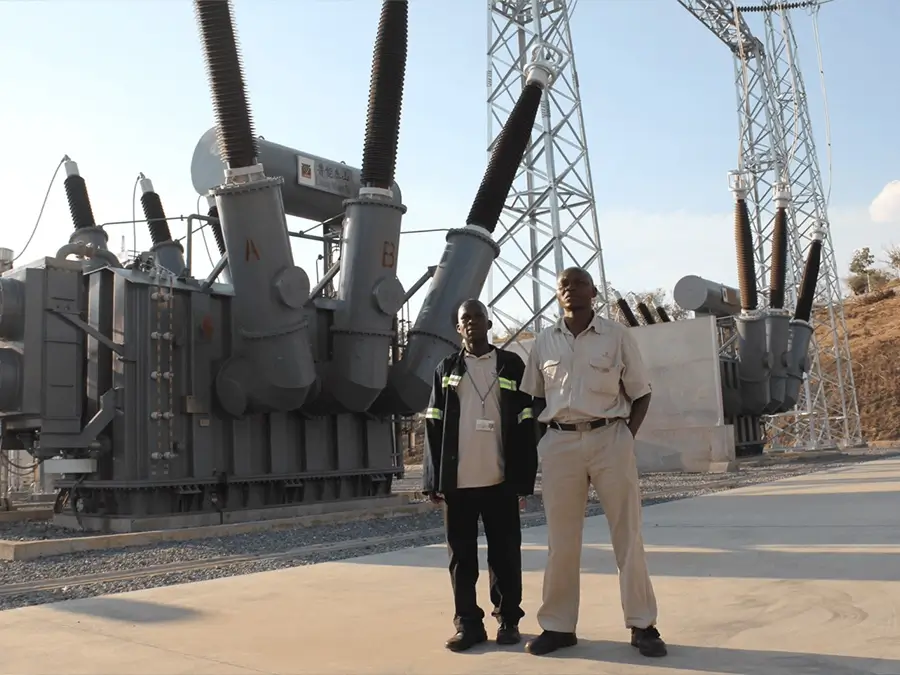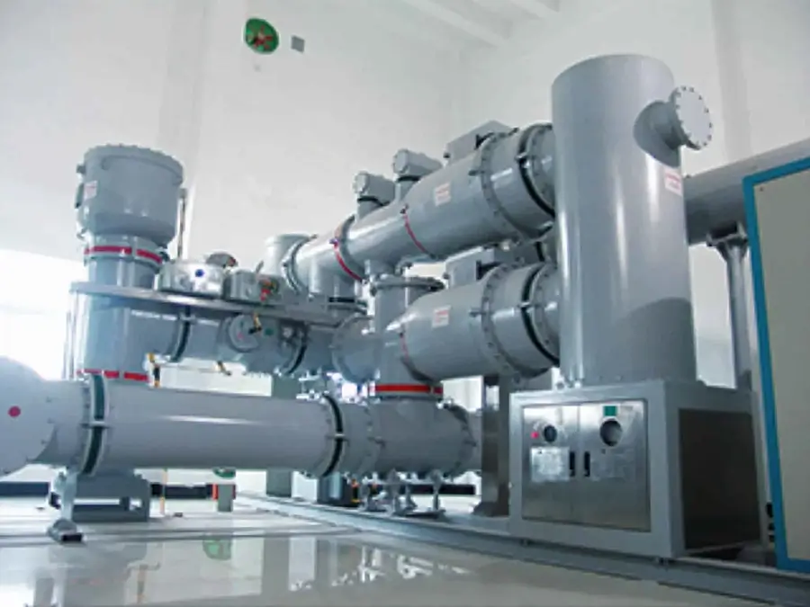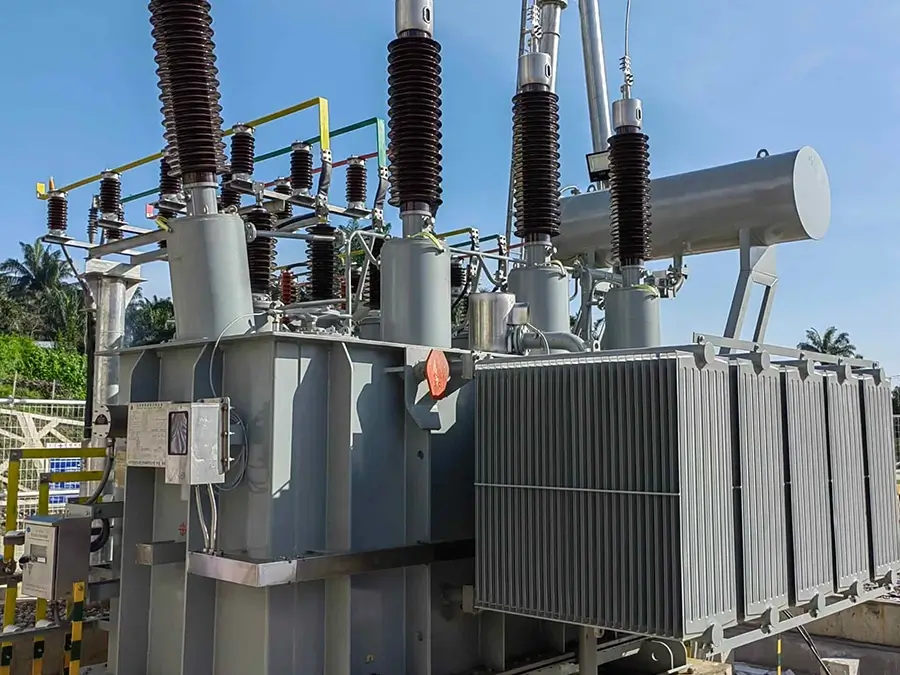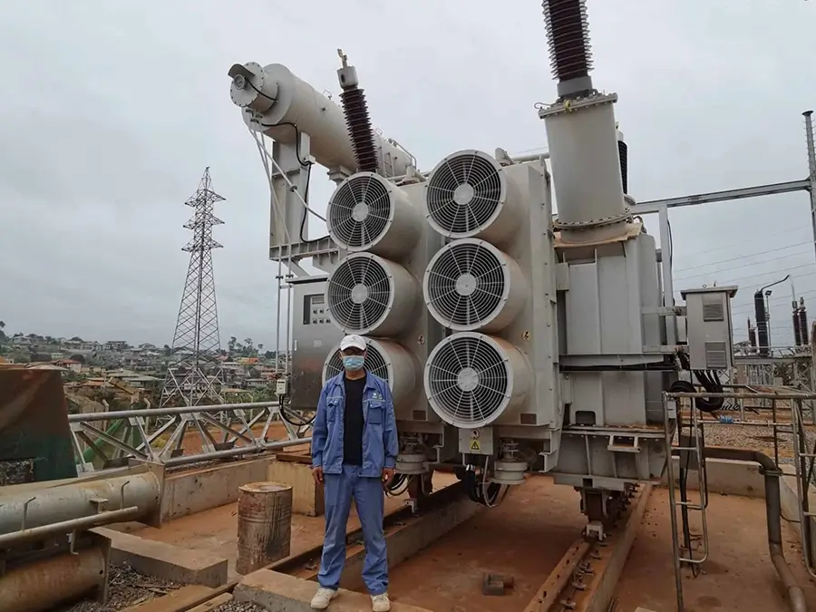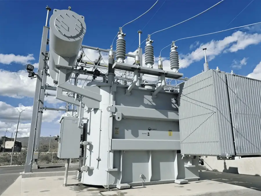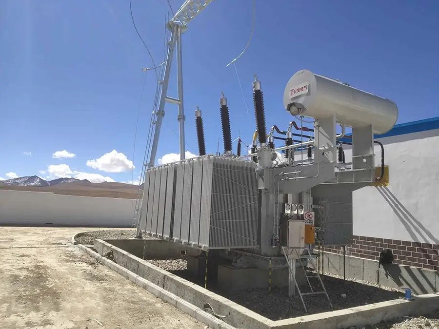






50kVA-3000kVA Power Oil Immersed Test Distribution Transformers
Overview
A test transformer is a special type of transformer used to generate high voltage for testing the insulation performance of various electrical equipment and insulating materials. It is mainly used for power-frequency withstand voltage tests, DC leakage current tests, etc., and is one of the basic equipment for high-voltage tests in power systems, industrial and mining enterprises, scientific research institutions and other places. Essentially, a test transformer is a step-up transformer. Through the principle of electromagnetic induction, it raises the relatively low input voltage to the high or extremely high voltage required for the test (ranging from several kV to several MV), thereby providing the test voltage for the test object.
Brief Introduction
Ⅰ. Product Introduction
1.Executive Standards: IEC 60076-3, IEEE
2.Voltage Levels
Series-excited test transformers can achieve higher voltages through multi-unit series connection
①Oil-immersed type: 5kV ~ 300kV (single unit)
②Gas-insulated type (SF6): 10kV ~ 600kV
③Insulated cylinder type: Up to 750kV (for ultra-high voltage tests)
3.Voltage Regulation Methods
①Frequency adjustable from 30-400Hz, used for induction withstand voltage tests.
②Contactless adjustment, output waveform distortion rate ≤ 1%, suitable for partial discharge tests with high waveform requirements.
③Continuous adjustment range: 0-250V, accuracy: ±1%, suitable for power-frequency withstand voltage tests.
Can be used with an electric control console for remote control, equipped with zero-position protection and overcurrent protection.
4.Frequency: 50Hz or 60Hz
5.Phase Number
①Single-phase (Mainly): More than 90% of test transformers are of single-phase structure, which is convenient for transportation and on-site use.
②Three-phase Application: Three-phase test transformers are used for the overall testing of three-phase equipment (such as distribution transformers) and need to be customized.
6.Connection Group
①Single-phase Transformer: The connection group label is Ⅰ.Ⅰ., with one end of the high-voltage winding grounded.
②Three-phase Transformer: Common Dyn11 or Yyn0, used in special testing scenarios (such as three-phase motor withstand voltage).
7.Impedance Voltage
①Oil-immersed type: ≤ 10% (standard type), ≤ 8% (low-impedance type)
②Gas-insulated type: ≤ 8%, suitable for high-voltage and low-current tests
③Insulated cylinder type: ≤ 5%, meeting the low-impedance requirements of AC pollution tests
8.Cooling Methods
Temperature rise control: Class H insulation allows a temperature rise of 125K, and the winding temperature ≤ 180℃.
Filled with SF6 gas at 0.25-0.45MPa, with insulation strength 2.5 times that of air, and maintenance-free.
Environmental adaptability: No liquefaction risk at -40℃ ~ +50℃, suitable for high-altitude areas.
Uses 25# transformer oil, with high heat dissipation efficiency, suitable for large-capacity and long-time tests.
Maintenance cycle: Oil change every 5 years, regular testing of oil withstand voltage (≥ 35kV) is required.
9.Oil-immersed type:
①Insulated cylinder type: Epoxy vacuum casting insulation, small in size and light in weight, suitable for frequent movement scenarios.
10.Protection Level
IP54 (dustproof and waterproof): Used in outdoor or high-dust environments.
IP66 (completely dustproof and water-jet proof): Suitable for humid environments or pollution level IV environments (creepage distance 3.1cm/kV).
Ⅱ. Operating Conditions
1.Environmental Requirements:
Altitude ≤ 1000m (conventional type). For altitude > 1000m, derating is required (derating by 5%-8% for every 1000m increase in altitude).
2.Applicable Temperature
Ambient temperature: -10℃ ~ +40℃ (standard type), -40℃ ~ +50℃ (wide-temperature type).
Winding temperature: Class H insulation allows a maximum temperature of 180℃, and short-term overload (120% capacity) should not exceed 30 minutes.
3.Application Scope
Power-frequency withstand voltage tests for transformers, current transformers, cables, insulators, circuit breakers, etc.
Induction withstand voltage tests for generator stator windings (frequency 100-400Hz).
Ⅲ. Test Types
1.Power-Frequency Withstand Voltage Test:
Voltage range: 10kV ~ 750kV, duration: 1-60 minutes.
2.DC Leakage Test:
Output DC voltage: 0-280kV, measured leakage current ≤ 100μA.
3.Impulse Withstand Voltage Test:
Standard lightning impulse (1.2/50μs) or switching impulse (250/2500μs), used to simulate overvoltage impulses.
4.Partial Discharge Test:
Sensitivity ≤ 10pC, used to locate insulation defects (such as inter-turn short circuits in windings).
Ⅳ. Component Inspection
1.Winding Inspection:
DC resistance test (deviation ≤ 2%), inter-turn withstand voltage test (2.5 times the rated voltage).
2.Bushing Inspection:
Power-frequency withstand voltage test (1.5 times the rated voltage), partial discharge amount ≤ 5pC.
3.Tap Changer Inspection:
Contact resistance of contacts ≤ 50μΩ, switching life ≥ 5000 times.
4.Overall Inspection:
Short-circuit withstand test (25 times the rated current for 2 seconds), temperature rise test (top oil temperature ≤ 95℃).
Ⅴ. Certification Types
1.International Certifications:
CE Certification: Complies with the EU Low Voltage Directive (LVD) and Electromagnetic Compatibility Directive (EMC).
②UL Certification: Certification by Underwriters Laboratories (suitable for products exported to the North American market).
Structural Features
Ⅰ. Product Features
1.As the core equipment for insulation performance testing in power systems, the product features of test transformers focus on four dimensions: high-voltage output capability, precise control accuracy, safety and reliability, and environmental adaptability, while integrating material innovation and intelligent technology. The following is a systematic analysis of its core features:
①Ultimate Balance between High-Voltage Output and Insulation Performance
Test transformers can provide a single-unit output voltage ranging from 10kV to 750kV, and higher voltage requirements can be achieved through a series-excited structure (e.g., 3 units of 150kV in series to reach 450kV). The insulated cylinder type test transformer adopts an epoxy cast cylinder shell and full insulation design, with a maximum single-unit voltage of 750kV, meeting the testing needs of ultra-high voltage equipment.
②Medium Innovation: Gas-insulated test transformers use SF6 gas insulation, with insulation strength 2.5 times that of air, partial discharge amount ≤ 5pC, and maintenance-free.
③Low Impedance and High Stability: The system impedance of the insulated cylinder type test transformer is ≤ 5%, meeting the low-impedance requirements of AC pollution tests; the impedance voltage of the oil-immersed test transformer is ≤ 10%, ensuring that the voltage waveform distortion rate during testing is < 1%.
2.Precise Control and Intelligent Testing Capability
①Automated Testing: Computer-controlled test transformers support automatic voltage boosting, withstand voltage timing, voltage reduction to zero, and have built-in overcurrent (high-voltage/low-voltage) and overvoltage protection, and can display parameters such as voltage, current, and time in real time.
②Data Recording and Analysis: Equipped with a high-speed thermal printer and RS232 interface, it can generate test reports and upload them to the Internet of Things platform to realize remote diagnosis and data analysis.
③Multiple Grounding: The transformer shell, high-voltage tail end, and operation box must be reliably grounded. During series tests, the shell of the secondary transformer is isolated by an insulating bracket.
④Rapid Protection: The insulated cylinder type test transformer adopts a rapid electronic protection device, which cuts off the power supply within 0.1 seconds when the test object breaks down, and its response speed is 5 times faster than that of traditional mechanical protection.
3.Modular Design and Portability Breakthrough
①Series Structure: Multiple single-unit test transformers (e.g., 3 units of 100kV) can be flexibly combined into a 300kV test system, meeting the withstand voltage requirements of large-capacity test objects (such as cables and GIS equipment).
②Multi-Voltage Compatibility: Lightweight test transformers realize rapid switching of three voltage grades (10kV/35kV/50kV) through tap windings and external copper bar switching, without the need for disassembly and adjustment.
③Gas-insulated Design: SF6 gas insulation reduces the volume and weight by 40%-65% compared with oil-immersed transformers of the same grade. For example, a 100kV gas-insulated test transformer weighs only 80kg and can be carried by a single person.
④Dry-type Structure: The dry-type test transformer with epoxy vacuum casting insulation weighs ≤ 150kg, supports vehicle-mounted transportation, and is suitable for field on-site testing.
Ⅶ. Product Advantages
1.Environmental Adaptability and Adaptation to Complex Scenarios
①High-Altitude Derating Design: For every 1000 meters increase in altitude, the capacity is derated by 5%-8%, while the insulation distance is increased by 20%, and the power-frequency withstand voltage test voltage is increased by 10%.
②Wide Temperature Range Operation: Standard test transformers can operate at -10℃ ~ +40℃, and wide-temperature type ( -40℃ ~ +50℃) is suitable for extremely cold or high-temperature environments.
2.Anti-Interference and Anti-Corrosion Properties
①Electromagnetic Compatibility: Computer-controlled test transformers adopt software and hardware anti-interference design, which can work stably in a strong electromagnetic environment, with a voltage measurement accuracy of 0.5 class.
②Pollution and Moisture Resistance: The insulated cylinder type test transformer is treated with a special coating, with a creepage ratio distance of 3.1cm/kV, suitable for pollution level IV environments.
3.In-depth Integration of Intelligent and Green Technologies
①SF6 Recovery System: Gas-insulated test transformers are equipped with gas recovery devices, with a leakage rate ≤ 0.5% per year, complying with the EU RoHS Directive.
②Energy-Saving Design: High-efficiency silicon steel sheet iron core and low-loss winding design, no-load loss ≤ 0.35%, 20% lower than traditional products.
③Real-Time Monitoring: Through high-precision sensors and 14-bit AD acquisition chips, it can display parameters such as high-voltage voltage, current, and insulation resistance in real time, with a resolution of 0.1%.
④Data Analysis: Automatically generate test reports, support historical data query and trend analysis, and help locate equipment aging laws.
4.Professional Expansion of Application Fields
①Series Resonance Test: For capacitive test objects such as cables and GIS equipment, high-voltage output under low-voltage excitation is realized by adjusting the frequency (30-300Hz), reducing the capacity requirement of test equipment.
②AC-DC Superposition Test: Complete the power-frequency withstand voltage and DC leakage tests of the equipment at one time, improving efficiency by 50%.
③Commissioning Test: Conduct power-frequency withstand voltage (10kV ~ 750kV) and DC leakage (0 ~ 280kV) tests on transformers, cables, insulators, etc.
④Preventive Test: Detect hidden dangers such as inter-turn short circuits in windings in advance through partial discharge detection (sensitivity ≤ 10pC) and insulation resistance testing.
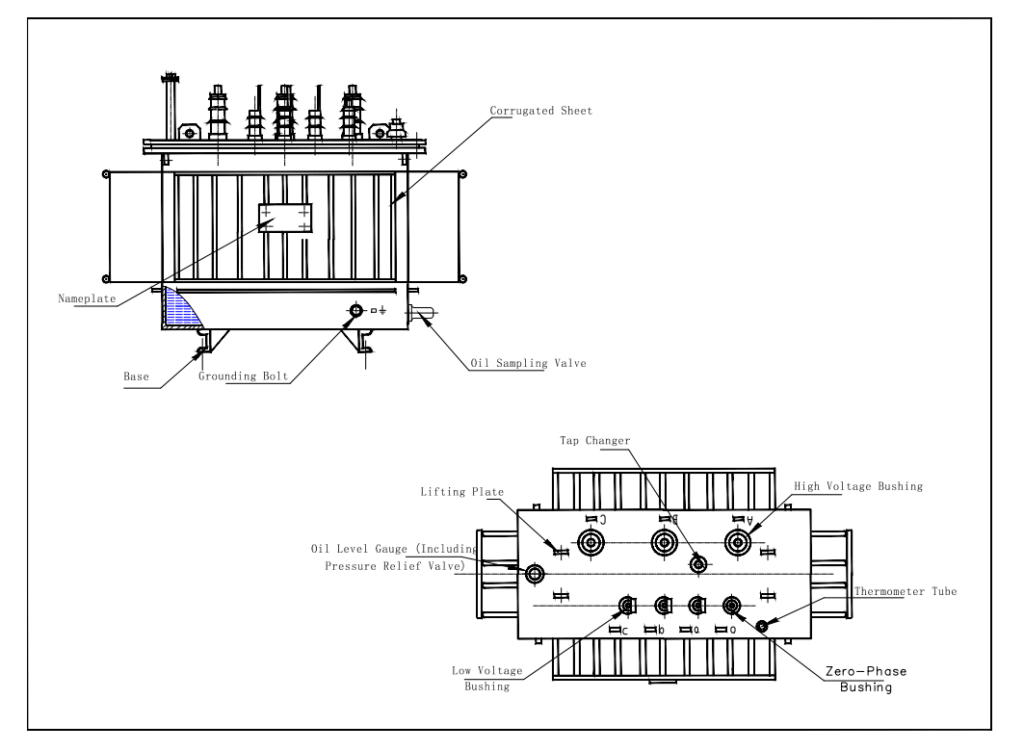
Product structure
Ⅰ. Product Features
1.As the core equipment for insulation performance testing in power systems, the product features of test transformers focus on four dimensions: high-voltage output capability, precise control accuracy, safety and reliability, and environmental adaptability, while integrating material innovation and intelligent technology. The following is a systematic analysis of its core features:
①Ultimate Balance between High-Voltage Output and Insulation Performance
Test transformers can provide a single-unit output voltage ranging from 10kV to 750kV, and higher voltage requirements can be achieved through a series-excited structure (e.g., 3 units of 150kV in series to reach 450kV). The insulated cylinder type test transformer adopts an epoxy cast cylinder shell and full insulation design, with a maximum single-unit voltage of 750kV, meeting the testing needs of ultra-high voltage equipment.
②Medium Innovation: Gas-insulated test transformers use SF6 gas insulation, with insulation strength 2.5 times that of air, partial discharge amount ≤ 5pC, and maintenance-free.
③Low Impedance and High Stability: The system impedance of the insulated cylinder type test transformer is ≤ 5%, meeting the low-impedance requirements of AC pollution tests; the impedance voltage of the oil-immersed test transformer is ≤ 10%, ensuring that the voltage waveform distortion rate during testing is < 1%.
2.Precise Control and Intelligent Testing Capability
①5Automated Testing: Computer-controlled test transformers support automatic voltage boosting, withstand voltage timing, voltage reduction to zero, and have built-in overcurrent (high-voltage/low-voltage) and overvoltage protection, and can display parameters such as voltage, current, and time in real time.
②Data Recording and Analysis: Equipped with a high-speed thermal printer and RS232 interface, it can generate test reports and upload them to the Internet of Things platform to realize remote diagnosis and data analysis.
③Multiple Grounding: The transformer shell, high-voltage tail end, and operation box must be reliably grounded. During series tests, the shell of the secondary transformer is isolated by an insulating bracket.
④Rapid Protection: The insulated cylinder type test transformer adopts a rapid electronic protection device, which cuts off the power supply within 0.1 seconds when the test object breaks down, and its response speed is 5 times faster than that of traditional mechanical protection.
3.Modular Design and Portability Breakthrough
①Series Structure: Multiple single-unit test transformers (e.g., 3 units of 100kV) can be flexibly combined into a 300kV test system, meeting the withstand voltage requirements of large-capacity test objects (such as cables and GIS equipment).
②Multi-Voltage Compatibility: Lightweight test transformers realize rapid switching of three voltage grades (10kV/35kV/50kV) through tap windings and external copper bar switching, without the need for disassembly and adjustment.
③Gas-insulated Design: SF6 gas insulation reduces the volume and weight by 40%-65% compared with oil-immersed transformers of the same grade. For example, a 100kV gas-insulated test transformer weighs only 80kg and can be carried by a single person.
④Dry-type Structure: The dry-type test transformer with epoxy vacuum casting insulation weighs ≤ 150kg, supports vehicle-mounted transportation, and is suitable for field on-site testing.
Ⅱ. Product Advantages
1.Environmental Adaptability and Adaptation to Complex Scenarios
①High-Altitude Derating Design: For every 1000 meters increase in altitude, the capacity is derated by 5%-8%, while the insulation distance is increased by 20%, and the power-frequency withstand voltage test voltage is increased by 10%.
②Wide Temperature Range Operation: Standard test transformers can operate at -10℃ ~ +40℃, and wide-temperature type ( -40℃ ~ +50℃) is suitable for extremely cold or high-temperature environments.
2.Anti-Interference and Anti-Corrosion Properties
①Electromagnetic Compatibility: Computer-controlled test transformers adopt software and hardware anti-interference design, which can work stably in a strong electromagnetic environment, with a voltage measurement accuracy of 0.5 class.
②Pollution and Moisture Resistance: The insulated cylinder type test transformer is treated with a special coating, with a creepage ratio distance of 3.1cm/kV, suitable for pollution level IV environments.
3.In-depth Integration of Intelligent and Green Technologies
①SF6 Recovery System: Gas-insulated test transformers are equipped with gas recovery devices, with a leakage rate ≤ 0.5% per year, complying with the EU RoHS Directive.
②Energy-Saving Design: High-efficiency silicon steel sheet iron core and low-loss winding design, no-load loss ≤ 0.35%, 20% lower than traditional products.
③Real-Time Monitoring: Through high-precision sensors and 14-bit AD acquisition chips, it can display parameters such as high-voltage voltage, current, and insulation resistance in real time, with a resolution of 0.1%.
④Data Analysis: Automatically generate test reports, support historical data query and trend analysis, and help locate equipment aging laws.
4.Professional Expansion of Application Fields
①Series Resonance Test: For capacitive test objects such as cables and GIS equipment, high-voltage output under low-voltage excitation is realized by adjusting the frequency (30-300Hz), reducing the capacity requirement of test equipment.
②AC-DC Superposition Test: Complete the power-frequency withstand voltage and DC leakage tests of the equipment at one time, improving efficiency by 50%.
③Commissioning Test: Conduct power-frequency withstand voltage (10kV ~ 750kV) and DC leakage (0 ~ 280kV) tests on transformers, cables, insulators, etc.
④Preventive Test: Detect hidden dangers such as inter-turn short circuits in windings in advance through partial discharge detection (sensitivity ≤ 10pC) and insulation resistance testing.
Ⅲ. Production Process
1.Raw Material Selection and Pretreatment Process
The performance of raw materials directly determines the insulation level and stability of the test transformer, which needs to go through multi-dimensional selection and pretreatment:
①Magnetic Conductive Material: High magnetic induction and low-loss silicon steel sheets (such as 35W250, 30W1300) are selected, with iron loss ≤ 2.5W/kg (50Hz, 1.7T), ensuring that the no-load loss of the iron core is reduced by 15%-20%; the lamination factor ≥ 0.96, reducing the magnetic circuit air gap.
②Conductive Material: The winding adopts high-purity oxygen-free copper wire (oxygen content ≤ 0.003%) or copper foil, with a conductivity ≥ 97% IACS. The surface is treated with tin plating or insulating paint to prevent oxidation and partial discharge.
③Insulating Material: Select suitable materials according to the type ——
Dry-type/Insulated cylinder type: Class H epoxy glass cloth board (temperature resistance 180℃), Nomex paper (breakdown strength ≥ 40kV/mm), vacuum-cast epoxy resin (volume resistivity ≥ 10¹⁴Ω・cm) are selected.
Oil-immersed type: Karamay 25# transformer oil (breakdown voltage ≥ 40kV/2.5mm), cable paper (thickness 0.08-0.12mm, tensile strength ≥ 2.5kN/m) are used.
2.Iron Core Manufacturing Process
①The iron core is the magnetic circuit core of the test transformer, and its manufacturing accuracy directly affects the no-load loss, noise and magnetic field distribution:
After lamination, vacuum curing is performed (0.1MPa vacuum degree, 120℃ × 6h) to enhance integrity; the insulation resistance of the iron core to the ground is tested to be ≥ 1000MΩ, and the no-load current deviation is ≤ ±5%.
②The cross-lamination method is adopted (the direction of each layer of laminations is alternated by 90°), fixed by positioning pins and insulating adhesive, with a lamination factor ≥ 0.95.
③For large iron cores, the segmented lamination + integral fastening process is adopted, bound by epoxy glass cloth tape (tension 50-80N) and fixed by clamps, ensuring that the overall flatness of the iron core is ≤ 0.5mm/m and reducing vibration noise (≤ 65dB).
④A CNC precision shearing machine (accuracy ±0.05mm) is used for cutting according to the design size to avoid burrs (≤ 0.03mm) and prevent partial electric field concentration from causing partial discharge.
⑤A stepped joint design (joint stagger angle 30°-45°) is adopted to reduce the magnetic circuit joint loss, which is 8%-10% lower than the traditional flat joint in terms of no-load loss.
3.Winding Winding and Insulation Treatment Process
The winding is the voltage conversion core of the test transformer, which needs to meet the requirements of high voltage withstand, low partial discharge and mechanical strength:
①Interlayer Insulation Treatment: After winding each layer of the winding, epoxy glass cloth or cable paper is laid, and hot-press curing (100-120℃, pressure 0.2MPa) is adopted to make the insulation layer fit closely and avoid air bubble residue.
②Overall Vacuum Drying: After winding, the winding is subjected to vacuum drying treatment (vacuum degree ≤ 10Pa, 130℃ × 12h) to remove moisture inside the insulation layer (moisture content ≤ 0.1%) and reduce dielectric loss.
4.Classification Assembly and Insulation Impregnation Process
The assembly and insulation processes of different types of test transformers are significantly different and need to be handled in a targeted manner:
①Sealed Shell Welding: The aluminum alloy shell is welded by argon arc welding (weld flatness ≤ 0.3mm). After welding, helium mass spectrometry leak detection is performed (leakage rate ≤ 1×10⁻⁹ Pa・m³/s).
②Insulated Cylinder Assembly: Insulating spacers are filled between the epoxy glass cloth cylinder (wall thickness ≥ 10mm) and the winding, and fastened by bolts to ensure uniform radial gap (deviation ≤ 1mm) and creepage ratio distance ≥ 3.1cm/kV.
③Oil Tank Assembly: The oil tank is welded with low-carbon steel plates (thickness 6-10mm) and undergoes a water pressure test (0.3MPa × 30min without leakage); heat dissipation tubes or fins are arranged inside (heat dissipation area ≥ 0.1m²/kVA) to ensure that the temperature rise is ≤ 65K.
5.Final Assembly and Electrical Accessory Integration Process
①Iron Core and Winding Assembly: Positioning shafts are used for positioning (coaxiality deviation ≤ 0.2mm). After assembly, insulation pressure plates and screws are used for fastening to ensure uniform axial pressing force (10-15kN/m) and avoid winding loosening.
②High-Voltage Bushing Assembly: Bushings (porcelain or silicone rubber) are installed after partial discharge testing (≤ 5pC @ 1.1 times the rated voltage). Nitrile rubber sealing rings (compression amount 20%-30%) are used for flange sealing to ensure reliable sealing.
③Tap Changer and Control Module:
The tap changer (no-load/on-load) undergoes mechanical life testing (≥ 10,000 operations), with a contact resistance ≤ 50μΩ.
Specification
50kVA-3000kVA Power Oil Immersed Test Distribution Transformers
| Rated Capacity | H.V. | L.V. | Connection symbol | No-load loss(w) | On-load loss(w) | Short circuit impedance | ||||
|---|---|---|---|---|---|---|---|---|---|---|
| S13 | S20 | S22 | S13 | S20 | S22 | |||||
| 30 | 6 6.3 10 10.5 11 |
0.4 | Dyn11 Yyn0 |
80 | 70 | 65 | 630/660 | 505/480 | 455/430 | 4 |
| 50 | 100 | 90 | 80 | 910/870 | 730/695 | 655/625 | ||||
| 63 | 110 | 100 | 90 | 1090/1040 | 870/830 | 785/745 | ||||
| 80 | 130 | 115 | 105 | 1310/1250 | 1050/1000 | 945/900 | ||||
| 100 | 150 | 135 | 120 | 1580/1500 | 1265/1200 | 1140/1080 | ||||
| 125 | 170 | 150 | 135 | 1890/1800 | 1510/1440 | 1360/1295 | ||||
| 160 | 200 | 180 | 160 | 2310/2200 | 1850/1760 | 1665/1585 | ||||
| 200 | 240 | 215 | 190 | 2730/2600 | 2185/2080 | 1970/1870 | ||||
| 250 | 290 | 260 | 230 | 3200/3050 | 2560/2440 | 2300/2195 | ||||
| 315 | 340 | 305 | 270 | 3830/3650 | 3065/2920 | 2760/2630 | ||||
| 400 | 410 | 370 | 330 | 4520/4300 | 3615/3440 | 3250/3095 | ||||
| 500 | 480 | 430 | 385 | 5410/5150 | 4330/4120 | 3900/3710 | ||||
| 630 | 570 | 510 | 460 | 6200 | 4960 | 4460 | 4.5 | |||
| 800 | 700 | 630 | 560 | 7500 | 6000 | 5400 | ||||
| 1000 | 830 | 745 | 665 | 10300 | 8240 | 7415 | ||||
| 1250 | 970 | 870 | 780 | 12000 | 9600 | 8640 | ||||
| 1600 | 1170 | 1050 | 940 | 14500 | 11600 | 10440 | ||||
| 2000 | 1360 | 1225 | 1085 | 18300 | 14640 | 13180 | 5 | |||
| 2500 | 1600 | 1440 | 1280 | 21200 | 14840 | 13360 | ||||
FAQ
1.How to select the appropriate test transformer capacity for my test object (such as cables, transformers)?
It is mainly calculated based on the capacitance of the test object and the test voltage. The formula is: Capacity P = 2 × π × Frequency (50Hz) × Test object capacitance (C, unit μF) × Test voltage (U, unit kV)² × 10⁻³ (unit kVA). The capacitance of the test object can be found in the equipment manual or measured. When selecting the capacity, a margin of 20%-50% should be left for the calculation result.
2.When the test transformer is boosting, the voltage cannot rise or even drops, and the current increases sharply. What is the reason?
This usually indicates that the test object is broken down. After breakdown, the loop current increases sharply, leading to an increase in the internal voltage drop of the transformer, and the output voltage decreases accordingly. At the same time, the overcurrent protection device may act. In this case, the test should be stopped immediately, and after the voltage is reduced and the power is cut off, the test object should be fully discharged and inspected.
3.The voltage is normal when no-load, but the voltage drops significantly after loading. Why?
Possible reasons include insufficient power supply capacity or too large internal resistance of the power line; the selected test transformer capacity is too small to compensate for the capacitive load current.
4.What are the differences between oil-immersed, dry-type and gas-insulated test transformers? How should I choose?
①Oil-immersed type: Mature technology, large capacity, low cost, but heavy, with the risk of oil leakage, and requires regular maintenance. Suitable for fixed laboratories.
②Dry-type: Maintenance-free, oil-free, flame-retardant, explosion-proof, lightweight, and environmentally friendly. Especially suitable for on-site tests that require frequent movement.
③Gas-insulated type (SF6): Lightest weight, smallest volume, maintenance-free, stable performance, and small partial discharge. Especially suitable for harsh environments such as high altitude and cold.
5.After the test is completed, why must a discharge rod be used for discharge?
Because the test object (such as cables, capacitors, large motors) will be equivalent to a large capacitor after the high-voltage test, which stores a large amount of charge and extremely high voltage. Direct contact can cause fatal electric shock. The discharge rod has a built-in resistor, which can safely and slowly release the charge to the ground, and it is an essential step to ensure personal safety.
6.The ground wire seems simple. Why is it repeatedly emphasized that it must be reliably grounded?
Reliable grounding is the lifeline of high-voltage tests. Its function is to ensure that the equipment shell, control box and test object remain at zero potential when an accidental breakdown occurs, preventing high voltage from intruding into the low-voltage side and protecting the safety of operators; it provides a discharge path for leakage current and discharge current, ensuring that the protection device can act correctly.
7.What is the "capacitive voltage rise effect"? What impact does it have?
The “capacitive voltage rise effect” refers to the phenomenon that when conducting an AC withstand voltage test on a capacitive test object, the capacitive current flows through the leakage reactance of the test transformer, generating a voltage increment in the same direction as the output voltage, resulting in the actual voltage acting on the test object being higher than the theoretical output value of the transformer. The impact is that the test object may bear a voltage exceeding the test standard, causing insulation damage. Therefore, for large-capacity capacitive test objects, a high-voltage divider must be used to measure the voltage directly on the high-voltage side, rather than relying solely on the conversion of low-voltage instrument readings.
Why Choose us ?
Built to last, engineered to perform.
Kete Transformer is a key national-level manufacturer specializing in transformers, recognized as a “Contract-Honoring and Promise-Keeping” enterprise, a high-tech enterprise, and a national-level enterprise technology center. It is recommended in the national directory for rural and urban power grid construction and renovation, as well as a recommended supplier of major electromechanical equipment for hydropower projects. Its products have been awarded the title of “National Quality Inspection Qualified Product – Quality Trustworthy Product” and “Nationally Recognized Product for Mechanical Industry Users.
Our Project
Our products not only dominate the domestic market but are also exported to more than 30 countries and regions, including Russia, Southeast Asia, Africa, and the Americas, serving industries such as power, municipal engineering, metallurgy, and petrochemicals.