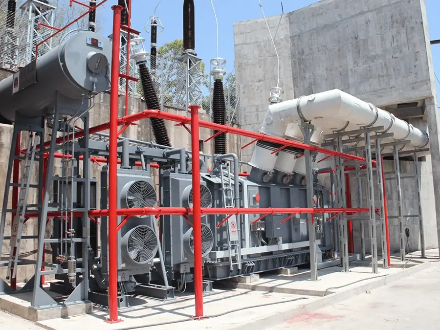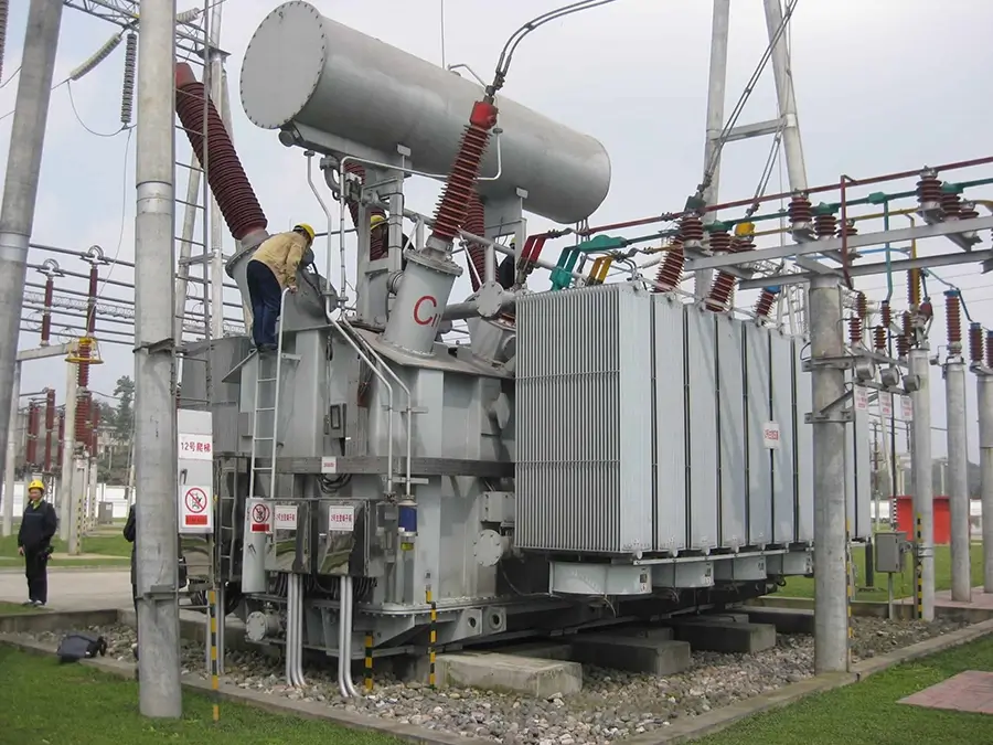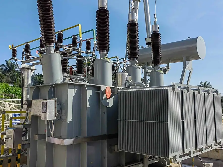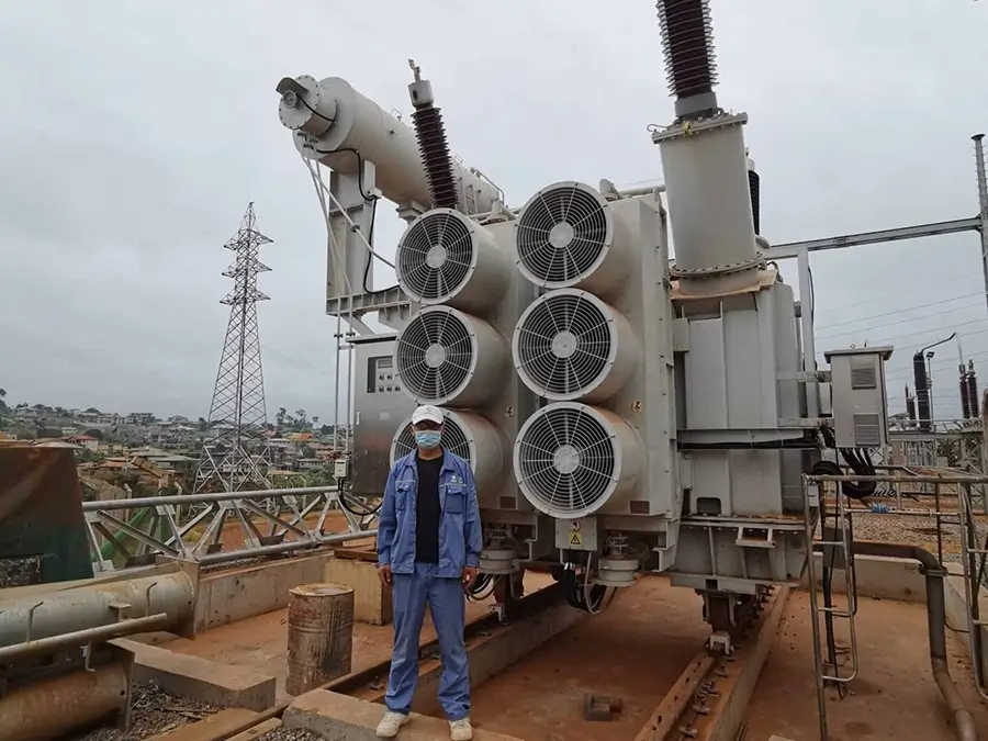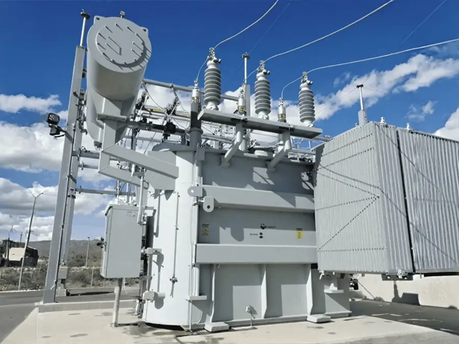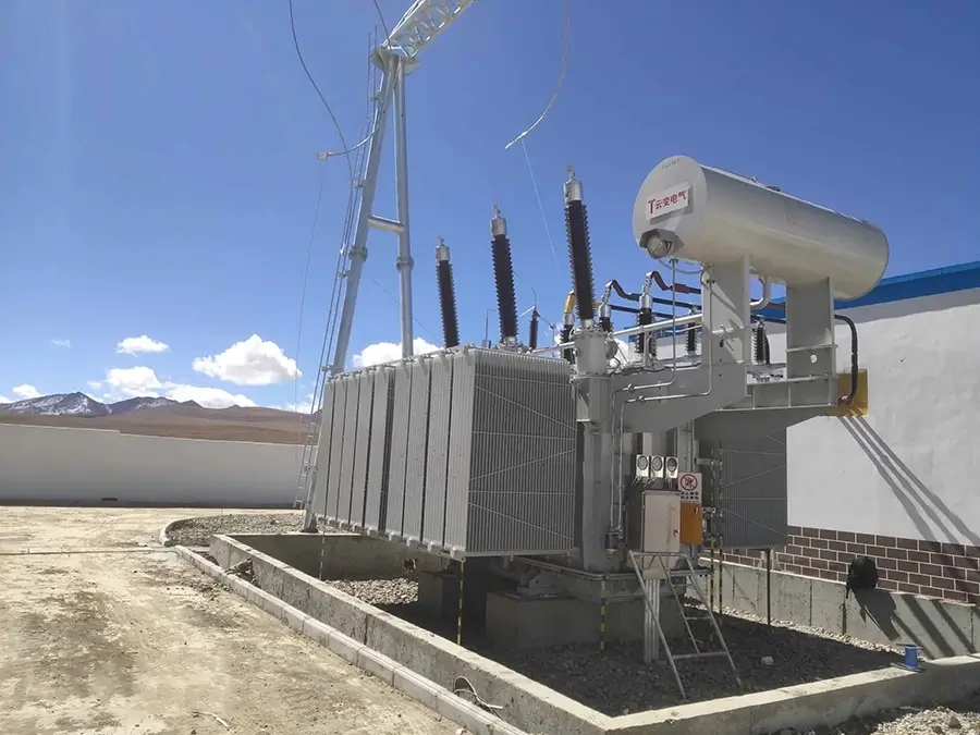





10KV Pad mounted transformer
Overview
10KV Pad mounted transformer is a compact power distribution device that integrates the transformer, high-voltage switchgear, and low-voltage outlet cable into a fully sealed metal enclosure. Designed specifically for outdoor terminal distribution scenarios, its core advantages lie in its fully sealed protection, corrosion resistance, durability, and easy installation. It is a mainstream device for terminal distribution in North America and globally.
Brief Introduction
Ⅰ.Brief Intrucodtion
1. Distribution Overview:
Customization Services: We offer highly customized Pad mounted transformer solutions. For space-constrained urban areas, we offer compact designs; for areas with extremely high safety requirements, we offer fully sealed, shock-proof designs; and for specialized environments, we offer corrosion-resistant and explosion-proof designs.
2.Implementation Standards: This product complies with multiple international standards, including IEEE, ANSI, and NEMA, primarily adhering to IEEE C57.12.20 (transformers), NEMA TR-27 (underground installation), and UL 1561 (dry-type transformers).
3.Voltage Levels:
①High-voltage side: 15kV, 25kV, 35kV, and other standard voltage levels, fully compatible with North American power grids.
②Low-voltage side: 480V/347V (60Hz standard), with support for custom voltages such as 208V.
Custom voltage levels are available to meet the requirements of different regional power grids.(Production range 6~35KV)
4.Voltage Regulation:
①On-load voltage regulation: Using advanced on-load tap changers, the taps are automatically or manually switched when the transformer is running under load, achieving continuous and precise voltage regulation. The voltage regulation range is usually ±5%, with fast response time and high voltage regulation accuracy, which is particularly suitable for commercial centers and industrial areas with high voltage quality requirements.
②Rated Capacity: Capacity ranges from 30kVA to 5500kVA (oil-immersed), with dry-type transformers available up to 2500kVA, meeting the power needs of users of varying sizes.
③Other Information: It utilizes a three-phase power supply system, primarily using Dyn11 connection groups, making it particularly suitable for non-linear load scenarios. Impedance voltage ranges from 4% to 6% and can be customized based on system characteristics. The cooling method is primarily oil-immersed self-cooling, with an IP67 protection rating, allowing for direct or semi-underground installation.
Ⅱ.Operating Conditions:
1.Altitude: No more than 1000 meters
2.Ambient Temperature: -25°C to +40°C
3.Relative Humidity: Daily average not exceeding 95%, monthly average not exceeding 90%
4.Maximum Monthly Average Temperature: +35°C
5.Maximum Annual Average Temperature: +20°C
6.Minimum Ambient Temperature: 25°C (outdoor)
7.Maximum Daily Temperature Difference: 25°C
8.Sunlight Intensity: 0.1W/cm² (0.5m/s)
9.Seismic resistance: 0.2g horizontal ground acceleration; 0.1g vertical ground acceleration
10.Installation location: Free from severe vibration, corrosive gases, explosive media, and heavy dust pollution
11.Applicable areas: Widely applicable to urban power grid transformation, residential communities, industrial parks, commercial centers, municipal projects, and new energy projects (such as wind power and photovoltaic power generation).
Ⅲ.Test Types:
1.Type Tests:
①Insulation Withstand Voltage Test
②Short-Circuit Withstand Capacity Test (25kA/2s)
③Temperature Rise Test
④Protection Level Test (IP67)
⑤Internal Arc Test (IEEE C37.20.7)
2.Routine Tests:
①Loop Resistance Measurement
②Power Frequency Withstand Voltage Test
③Mechanical Operation Test
④Transformer Parameter Test
3.Special Tests:
①Noise Test
②EMC Test
③High and Low Temperature Cycle Test
④Salt Spray Corrosion Test
Ⅳ.Component Testing:
1.Transformer: Insulating Oil Withstand Voltage (Oil-fired Transformer), Partial Discharge (Dry-fired Transformer), Temperature Rise.
2.High-Voltage Components: Fuse Characteristics, Surge Arrester Residual Voltage.
3.Low-Voltage Units: Circuit Breaker Capacity, Busbar Contact Resistance.
4.Enclosure: Dust and Water Resistance (IP), Mechanical Strength (Wind and Vibration Resistance).
Ⅴ.Certification Types:
1.International: IEC 62271-202, IEEE C57.12.00. North American Certifications: UL 1561 (Dry-Type Transformer), UL 50E (Enclosure), CSA C227.4
2.China: GB/T 17467 (National Standard), CQC Certification
3.Other Certifications: CE (EU), AS/NZS (Australia and New Zealand), NOM Certification (Mexico)
Structural Features
Product Features
Ⅰ.Product Features:
1.Fully Sealed Safety Design: Featuring a fully insulated and sealed structure with an IP67 rating, it offers complete protection against electric shock. No safety fence is required, allowing for direct installation in public areas.
2.Compact Modular Design: The integrated enclosure structure houses the high-voltage switchgear, transformer, and low-voltage equipment in a highly compact package, occupying only one-quarter the footprint of a traditional substation, making it ideal for densely populated urban areas.
3.Suitable for Extreme Environments: The enclosure utilizes a special anti-corrosion treatment (aluminum-zinc-plated steel plate + heavy-duty anti-corrosion coating), offering a temperature range of -60°C to +60°C and UV resistance, making it suitable for a variety of harsh environments.
4.Intelligent Monitoring System: Built-in temperature, humidity, and pressure sensors support remote monitoring and fault diagnosis, and an optional IEC 61850 communication interface is available.
Ⅱ. Product Advantages
1.Efficient Installation: Pre-installed and commissioned at the factory, only foundation installation and simple wiring are required on-site, reducing installation time to 1-2 days, significantly less than the several weeks required for traditional substations.
2.High Safety Redundancy: The UL 1551-certified high-voltage switch has strong short-circuit breaking capacity, and the transformer’s short-circuit-resistant design and explosion-proof enclosure reduce accident risks.
3.Easy Maintenance: Modular components enable quick replacement, and the sealed enclosure reduces dust and moisture intrusion, reducing routine maintenance frequency.
Ⅲ. Product Benefits
1.Efficient Installation and Low Cost:
①Pre-installed and commissioned at the factory, only cable connection and anchoring are required on-site, with an installation time of 4 hours or less (traditional transformers require 1-2 days).
②No equipment room is required, reducing land occupation costs by 60%, making it suitable for densely populated urban areas or land-scarce locations.
2.Safe and Reliable Operation:
①The high-voltage side features an elbow-type cable connector (compliant with IEEE 386) with a mechanical interlock to prevent live operation.
②The transformer’s short-circuit withstand capability reaches 25kA/1s (IEEE C37.20.2), and its short-circuit-resistant design reduces the risk of failure.
③The oil-immersed transformer is equipped with a pressure relief valve, oil level gauge, and temperature alarm, ensuring an average annual downtime of ≤2 hours in extreme environments.
3.Flexible Adaptability:
①Residential Areas: Low noise design (≤55dB@1m) and landscape-colored housing (customizable RAL color palette) blend seamlessly into the community environment.
②Industrial Areas: Reinforced housing for impact resistance (≥20J) and forced air cooling adapt to high-load, high-temperature environments.
③New Energy Applications: Integrated photovoltaic/wind power grid-connected interfaces and bidirectional electricity metering (ANSI C12.20 standard) are available.
ⅣEvidence
1.Certification and Testing:
①UL 1551, CSA, IEEE C37.20.7, and other certifications have been achieved.
②Type testing has verified a short-circuit withstand capability of 25kA/2s.
③IP67 protection rating has been certified.
④Verified for -60°C low-temperature operation.
2.Application Cases:
①Successfully deployed in over 300 commercial locations across North America.
②Installation efficiency has increased by 70%.
③Five-year failure rate is less than 1.5%.
④A power company’s 1,000 units have operated continuously for 12 years without major failures.
3.Measured Data:
①Third-party testing reports indicate a noise level of ≤55dB@1m.
②Energy efficiency testing shows no-load losses are 30% lower than the DOE 2016 standard.
③Temperature rise testing shows a maximum temperature rise of ≤65K.
Product structure
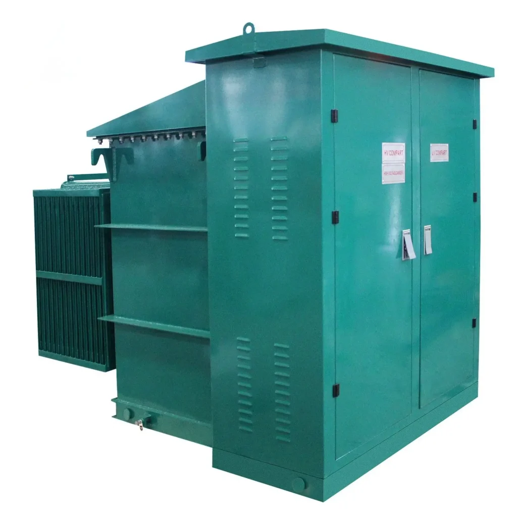
The American-style pad-mounted transformer features a fully sealed, compact, and maintenance-free integrated design. Its structure has been carefully optimized to ensure maximum safety, reliability, and durability in harsh outdoor environments. The overall structure is centered around a sturdy, sealed, welded metal enclosure with strategically designed internal compartments, integrating all medium-voltage, transformation, and low-voltage distribution functions.
Ⅰ.Overall Structural Design
1. Design Standards
①Transformer:Complies with IEEE C57.12.20 (Pad-Mounted Equipment), IEEE C57.12.00 (General Requirements), and IEEE C57.12.90 (Test Standards).
②Enclosure:Complies with NEMA TR-27 (Integrity of Underground Transformer Enclosures) and NEMA 250 (Degrees of Protection), ensuring protection against dust, water, and external physical impact.
③Switchgear:Complies with UL 347 (Medium-Voltage Switchgear), UL 891 (Switchgear), and IEEE C37.20.3 (Medium-Voltage Switchgear Standard).
④Seismic Resistance:Designed to meet the seismic requirements of IEEE 693 or user-specified areas (e.g., California Seismic Zone 4), ensuring stability during earthquake activity.
2. Modular Functional Composition
The interior of the box-type transformer is logically divided into three main functional areas, physically separated by sturdy metal partitions to ensure safety and convenient maintenance:
①High-Voltage Compartment: Houses all medium-voltage components, such as elbow-type cable plugs, fault indicators, lightning arresters, and fused load switches or circuit breakers. This compartment features a retractable operating panel for easy operation and maintenance, and is equipped with strict mechanical and electrical interlocks to prevent accidental operation while energized.
②Transformer Compartment: The core area houses the oil-immersed distribution transformer. It is designed with ample heat dissipation space and safety measures.
③Low-Voltage Compartment: Houses the low-voltage circuit breaker, metering instruments, intelligent monitoring unit, and outgoing terminal blocks. It has a separate, lockable door, restricting access to authorized personnel only.
Ⅱ.Core Structural Components
1.Cabin Structure
①Material:
•Exterior: Made of high-strength, corrosion-resistant ASTM A792 galvalume steel or 304/316L stainless steel (suitable for highly corrosive environments such as coastal areas), with a thickness of ≥2.5mm.
•Internal Frame: Utilizes ASTM A123 hot-dip galvanized steel beams, providing strong structural support and wind pressure resistance of ≥1500Pa, ensuring deformation during hoisting and transportation.
②Layout and Construction:
•Integral Welding: The tank utilizes a continuous welding process to ensure overall airtightness and waterproofing. The welds are uniform and smooth, with no gaps or missing welds.
•Top Design: A distinctly sloped roof (slope ≥5°) effectively prevents rainwater accumulation. Weather-resistant sealing strips are used to seal the roof and tank.
•Ventilation and Heat Dissipation: Concealed rain-proof louvers at the bottom and top of the enclosure create convection air ducts, ensuring natural heat dissipation. Stainless steel insect screens are standard on the inside of the louvers to prevent small animals from entering.
•Surface Treatment: After a rigorous seven-step pre-treatment (degreasing, water washing, surface conditioning, phosphating, water washing, pure water washing, and drying), the enclosure is coated with a high-quality polyester powder coating with a coating thickness of ≥ 80μm. The coating has passed the ASTM B117 salt spray test for ≥ 1000 hours and is UV-resistant.

2. Transformer Compartment
①Independent Sealed Design: Completely isolated from the high- and low-voltage compartments, preventing transformer oil or faults from affecting other equipment.
②Safety Protection:
•Pressure Relief Device: Located above the transformer, it rapidly releases pressure and triggers an indicator flag to pop out when internal pressure rises abnormally, preventing the enclosure from exploding.
•Fireproof Baffle: Made of UL 94 V-0 flame-retardant material, it effectively prevents the spread of flames.
③Temperature Control System: A built-in PT100 temperature sensor monitors oil temperature in real time. An optional forced air cooling system is available (with temperature-controlled start and stop, typically set at 75°C for start and 65°C for stop).
②Secondary Wiring: The transformer’s low-voltage bushing is connected to the low-voltage cabinet via an insulated busbar or flexible cable. Insulation sheaths are installed at the connection points to ensure safety.

3. HV & LV Equipment Layout
①High-Voltage Side:
•Connection Method: A standard 200A American elbow-type cable plug (IEEE 386 Standard) is used for a fully insulated, fully sealed, plug-in connection, ensuring safety and convenience. Both loop feed and radial feed wiring are supported.
•Protection Devices: Built-in dual time-current characteristic (T-C) backup fuses provide precise overload and short-circuit protection. A ZnO surge arrester protects against switching overvoltage and lightning overvoltage.
②Low-Voltage Side:
•Outgoing Switches: Utilize UL 489-certified frame circuit breakers or molded case circuit breakers for high breaking capacity.
•Busbar System: Electrolytic copper busbars (ASTM B187) with tin or silver plating to reduce contact resistance and enhance oxidation resistance. All busbar connections are torque-controlled and feature UL 746C-certified high-strength insulation sheaths and phase color markings.
•Intelligent Monitoring: An optional integrated intelligent monitoring unit monitors current, voltage, power, oil temperature, and other parameters, supporting RS485/DNP3.0/IEC 61850 communication protocols for remote data transmission.

Ⅲ. Special Structural Design
1. Comprehensive Safety Protection
①Five-Prevention Interlock Mechanism:
•Prevents operating the load switch under load (the operating panel cannot be opened when the switch is closed).
•Prevents accidental entry into live compartments (the automatic grounding switch can only be operated after the operating panel is opened).
•Prevents closing the grounding switch while energized.
•Prevents closing the load switch while the grounding switch is in the closed position.
•Prevents accidental tripping or closing of the circuit breaker.
②Anti-collision and anti-theft features: Optional steel anti-collision barriers ≥4mm thick are available around the enclosure. All door locks utilize three-point anti-theft lock cylinders that require special tools to effectively prevent unauthorized intrusion.
③Grounding system: A dedicated, clearly marked main grounding terminal is provided, with a cross-sectional area that complies with IEEE 80 standards and ensures a grounding resistance of ≤5Ω.
2. Excellent Environmental Adaptability
①Ventilation and Dehumidification: In addition to natural ventilation, an optional automatically controlled IP55-rated forced ventilation fan is available. Anti-condensation heaters are standard in the high-voltage and low-voltage compartments, automatically activated and deactivated by the temperature and humidity controller to maintain a humidity of ≤60%RH. Noise Reduction ②Measures: The transformer compartment’s internal walls can be installed with high-efficiency sound-absorbing cotton (density ≥48kg/m³) to keep equipment operating noise within a range of ≤55dB@1m, meeting residential noise standards.
3.Intelligence & Scalability
①Plug-and-Play Interfaces: The pre-installed IoT communication interface bulkhead supports the easy installation of various sensors and communication modules (such as 4G/5G routers).
②Easy Expansion: The number of low-voltage outgoing circuits (4-12) can be customized according to needs. The bottom features a fully removable cable entry cover, providing ample cable entry space and a high bending radius, facilitating future capacity expansion or modifications.
IV. Transportation and Installation Structure
1. Lifting Design:
High-strength lifting lugs (M42 or higher) are installed at the four corners of the enclosure, with a safety factor of ≥4 times the total equipment weight (when fully loaded with transformer oil). The lug positions have been optimized using Finite Element Analysis (FEA) to ensure balanced lifting and prevent enclosure deformation.
2. Foundation and Positioning:
•Foundation Requirements: A reinforced concrete foundation ≥ 300mm thick (levelness ≤ 3mm/m) must be cast and pre-buried with anchor bolts conforming to ASTM A307.
•Installation Method: The equipment is hoisted directly onto the foundation and secured with anchor bolts. A shock-absorbing gasket may be installed between the bottom of the equipment and the foundation. Cables can be routed through waterproof glands from the bottom or side.
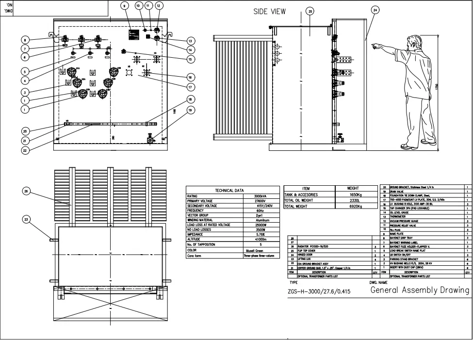
Specification
10KV Pad mounted transformer
| Capacity KVA |
HV | LV | Connection | Mode | No-load loss KW |
On-load loss KW |
Impedance % |
|---|---|---|---|---|---|---|---|
| 75 | 7.2~12.47 7.62~13.2 7.957~13.8 19.92~34.5 or others |
0.24 0.277 0.347 0.48 0.6 or others |
Dyn11 Yyn0 or others |
Loop feed Radial feed |
0.180 | 1.250 | 4.0~6.0 |
| 112.5 | 0.200 | 1.500 | |||||
| 150 | 0.280 | 2.200 | |||||
| 225 | 0.400 | 3.050 | |||||
| 300 | 0.480 | 3.650 | |||||
| 500 | 0.680 | 5.100 | |||||
| 750 | 0.980 | 7.500 | |||||
| 1000 | 1.150 | 10.300 | |||||
| 1200 | 1.320 | 12.120 | |||||
| 1500 | 1.640 | 14.500 | |||||
| 2000 | 2.160 | 20.645 | |||||
| 2500 | 2.680 | 27.786 | |||||
| 3000 | 3.300 | 30.300 | |||||
| 3750 | 4.125 | 37.875 |
FAQS
Ⅰ.Basic Concepts
1. What is a Pad-Mounted Transformer?
A Pad-Mounted Transformer is a compact outdoor power distribution device that integrates the transformer, high-voltage switchgear, and low-voltage outgoing line device into a fully sealed metal enclosure. It does not require a separate equipment room and can be installed directly on concrete floors or in green belts. It is suitable for 2.4-35kV distribution systems and serves as a terminal power conversion and distribution device. Its design complies with North American standards such as ANSI and IEEE, and is widely used in terminal power distribution scenarios in North America and globally.
2. How does it differ from an American-style prefabricated substation?
①Structural Differences: The Pad-Mounted Transformer features a single-chamber, integrated design, focusing on basic power distribution functions (high voltage – transformation – low voltage). American-style prefabricated substations are mostly modular and can integrate more expanded functions (such as reactive power compensation and intelligent monitoring).
②Application Scenario: The Pad-Mounted Transformer focuses on end-users (such as residential and commercial areas), while the Pad-Mounted Transformer is suitable for medium- and high-voltage distribution hubs (such as industrial parks and grid nodes).
③Capacity Range: The former is mainstream 30-1600kVA, while the latter can reach 1600-5500kVA, suitable for larger loads.
Ⅱ. Technical Parameters
3. What are the standard voltage levels and capacity ranges?
①Voltage: High-voltage side: 2.4kV/7.2kV/12.47kV (mainstream in North America)/24kV/35kV, with customizations available for 11kV/15kV, etc.; Low-voltage side: 120/240V (single-phase), 480V/277V (three-phase).
②Capacity: 50kVA (small communities) to 1000kVA (industrial parks). Oil-immersed type is the main option, with dry-type options available for customization.
4. What are the protection levels and corrosion resistance?
①nclosure protection rating: IP65 (dustproof and high-pressure water jet-proof), internal compartment IP2X (electric shock-proof).
②The housing is constructed of galvanized steel (ASTM A792) or 304 stainless steel, with an anti-corrosion coating that has passed the ASTM B117 salt spray test for ≥500 hours. Custom coatings with ≥1000 hours are available for use in highly corrosive environments such as coastal areas.
Ⅲ. Installation and Commissioning
5. What are the installation foundation requirements?
①A concrete platform (thickness ≥200mm, levelness ≤3mm/m) with four pre-buried M16 anchor bolts (ASTM A307) is required.
②A cable trench (width ≥600mm) and a grounding grid (grounding resistance ≤5Ω) must be provided, with a surrounding clearance of ≥1.5m.
6. Is on-site splicing required? What are the transportation restrictions?
①The integrated design eliminates the need for on-site splicing, and the length of a single cabin is ≤12m (in compliance with road transport restrictions).
②During transportation, the cabin must be secured on a dedicated pallet to avoid excessive vibration (in compliance with ISTA 3A transportation standards).
IV. Operation and Safety
7. What routine maintenance is required?
①Monthly: Check the oil level gauge (oil-immersed), enclosure sealing, and vent blockages.
②Annually: Infrared temperature measurement (busbar connection points), ground resistance test, protective device calibration, and insulation resistance test (≥1000MΩ).
8. How to cope with high or low-temperature environments?
①High temperature: Units above 630kVA can be equipped with a forced air cooling system (temperature-controlled start/stop, threshold ≤90°C) to enhance heat dissipation.
②High temperature: Oil-immersed units use -40°C anti-condensation insulating oil, and an optional in-cabin heater (automatic start/stop, maintaining a temperature ≥5°C to prevent condensation) is available.
V. Model Selection and Customization
9. How to select a model based on project requirements?
①Residential areas: 50-200kVA: Choose a low-noise model (≤55dB@1m) with a landscape-friendly enclosure.
②Industrial areas: 500-1000kVA: Choose a high short-circuit withstand rating (25kA/1s) with forced air cooling.
③New energy scenarios: Customized grid-connected protection devices (compliant with IEEE 1547) and bidirectional electricity meters (ANSI C12.20) are required.
10. What customization options are supported?
We can customize voltage levels (e.g., 27kV), housing materials (316 stainless steel), monitoring functions (IEC 61850 protocol), anti-theft locks, and more to meet specific environmental or functional requirements.
VI. Common Troubleshooting
11. What should I do if the transformer overheats?
①Check whether the air cooling system is activated (for large-capacity models) and whether the load exceeds the limit (must comply with IEEE C57.91 load guidelines).
②Clean the heat sink from dust and ensure the ventilation holes are unobstructed. If the alarm persists, contact a technician to inspect the winding insulation.
12. Why is the high-voltage side unable to close?
Prioritize: Check whether the elbow cable connector is properly plugged in (a click should be heard to confirm) and whether the mechanical interlock is reset (preventing live operation).
Ⅶ.Other Questions
13. What is the warranty period? What is the after-sales service like?
①The standard warranty is 1 years, and the transformer itself can be extended to 2 years.
②We provide 24/7 technical support, with a fault response time of ≤ 2 hours. Spare parts and on-site repairs (including travel expenses) are provided free of charge during the warranty period.
14. What application cases can you refer to?
Typical cases include North American residential power distribution (50-200kVA), industrial parks (500-1000kVA), and photovoltaic power station grid connection. Project photos and operating data reports are available.
Why Choose us ?
Built to last, engineered to perform.
Kete Transformer is a key national-level manufacturer specializing in transformers, recognized as a “Contract-Honoring and Promise-Keeping” enterprise, a high-tech enterprise, and a national-level enterprise technology center. It is recommended in the national directory for rural and urban power grid construction and renovation, as well as a recommended supplier of major electromechanical equipment for hydropower projects. Its products have been awarded the title of “National Quality Inspection Qualified Product – Quality Trustworthy Product” and “Nationally Recognized Product for Mechanical Industry Users.
Our Project
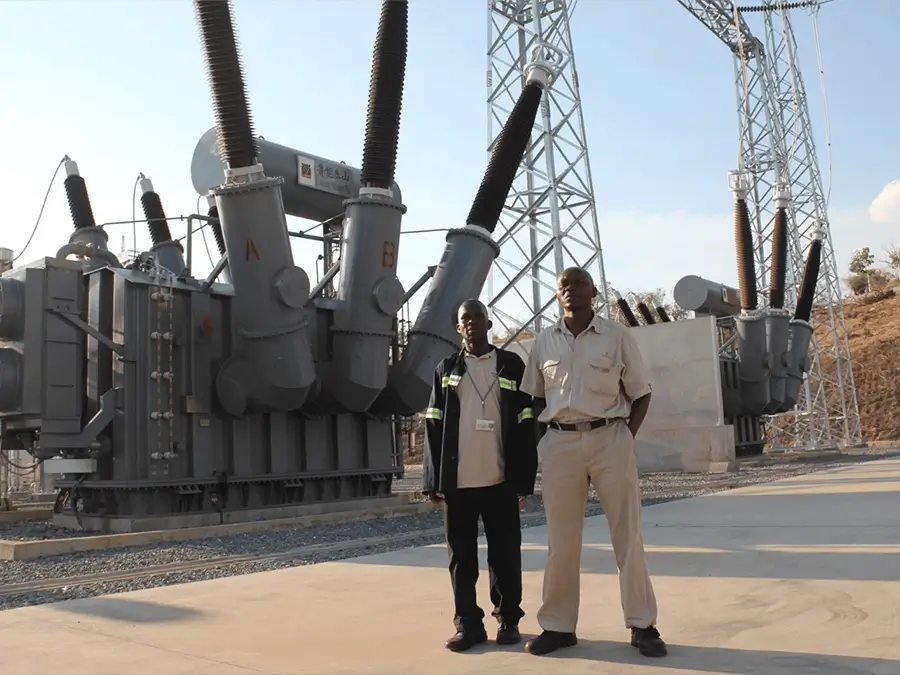
Our products not only dominate the domestic market but are also exported to more than 30 countries and regions, including Russia, Southeast Asia, Africa, and the Americas, serving industries such as power, municipal engineering, metallurgy, and petrochemicals.