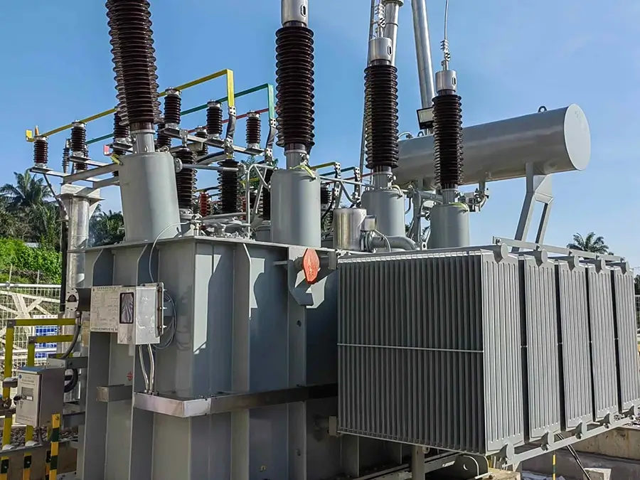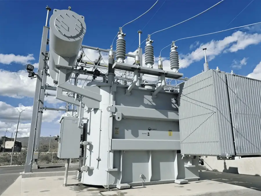






10kV High Overload Oil-Immersed Transformer with Copper Core and Low Noise Design
Overview
A high-overload transformer is a special power transformer that can operate beyond its nameplate capacity without affecting its normal service life. It is mainly used in scenarios with low annual average load rates but high short-term loads, helping to save significant equipment investment and electricity costs. Through advanced materials, special structural design, and intelligent control, high-overload transformers achieve safe and reliable short-term overload capability. It provides an economical, flexible, and efficient power supply solution for occasions that need to cope with severe load fluctuations or have short-term capacity expansion expectations.
Brief Introduction
Ⅰ. Product Introduction
1.Executive Standards: T/GES 001-2017, GB 1094 Series
2.Voltage Level: The high-voltage side is commonly 10kV, and the low-voltage side is 0.4kV; higher voltage levels such as 110kV are also available.
3.Voltage Regulation Method: No-load voltage regulation (power outage is required for tap adjustment)
4.High-Voltage Tap Range: ±5% or ±2×2.5%. It is used to adjust the output voltage within a qualified range when the grid voltage fluctuates.
5.Rated Capacity: Common range is 30kVA to 500kVA
6.Frequency: 50Hz or 60Hz
7.Phase: Three-phase or single-phase
8.Connection Group: Dyn11, Yyn0
9.Impedance Voltage: 4%
10.Cooling Method:
① Oil-immersed self-cooling (ONAN);
② Dry-type self-cooling (AN);
③ Dry-type forced air cooling (AF)
11.Protection Class: The oil tank of oil-immersed transformers provides protection itself; dry-type transformers usually have IP20 (protection against solid foreign objects).
12.Insulation Class: Usually Class A; dry-type transformers commonly use Class F (155℃) or Class H (180℃); the insulation heat resistance level of high-overload distribution transformers meets the applicable conditions of insulation limit values for Class B and above.
Ⅱ. Operating Conditions
1.Altitude: ≤1000m (customization is required for ultra-high altitude)
2.Ambient Temperature: -20℃ ~ +45℃
3.Application Scope: Photovoltaic/wind power converging and boosting, energy storage system interfaces, metallurgical and chemical industries (short-term impact loads of arc furnaces and electrolytic cells), rail transit traction substations, commercial areas (evening load peaks); suitable for occasions with low annual average load rates and heavy short-term or periodic loads.
Ⅲ. Test Types
①Routine tests (mandatory for each unit)
②Type tests (to verify design)
Ⅳ. Component Inspection
1.Coil DC resistance, voltage ratio and connection group label, impedance voltage, no-load loss test;
2.No-load current, load loss, insulating oil test (for oil-immersed type), partial discharge (for dry-type), applied voltage withstand test and induced voltage withstand test, sealing test;
3.On-load tap-changer test to ensure that each component and the overall performance meet the design standards.
Ⅴ. Certification Types
International: TUV, UL, KEMA, CE.
Structural Features
Ⅰ. Product Features
1.Outstanding Overload Capability
① High-overload transformers do not simply “withstand” overload; instead, their overload capability is accurately quantified through careful design.
② Typical overload curve: It can usually operate safely at 1.5 times the rated capacity for 6 hours; at 1.75 times the rated capacity for 3 hours; and even at 2.0 times the rated capacity for 1 hour (specific values vary depending on manufacturer design and standards).
③ Value: This means users do not need to purchase a much larger ordinary transformer for occasional peak loads, thus saving significant initial investment, installation space, and electricity costs from no-load losses during daily low-load operation.
2.Excellent Heat Dissipation Performance
① High-overload transformers enhance heat dissipation through multiple methods:
Optimized heat dissipation structure: Adopt corrugated oil tanks (to increase heat dissipation area), enlarged heat sinks, or additional heat dissipation pipes. Some products also have preset interfaces or devices for forced air cooling (AF), which start fans during overload to significantly improve heat dissipation capacity.
② Use of high thermal conductivity media: Oil-immersed transformers often use high-flash-point oil or natural ester insulating oil (vegetable insulating oil). The latter not only has a high flash point and good fire resistance but also has better cooling performance of its natural ester molecules than mineral oil.
3.High Heat-Resistance Class Insulation System
① High temperature is the enemy of insulation aging. High-overload transformers ensure their service life during overload by improving the heat resistance class of insulation materials.
② Material upgrade: Winding conductors use Class C or Class H insulation materials such as NOMEX® paper and polyimide film, or high heat-resistant polyester fiber paper. The insulating paper of oil-immersed transformers usually uses high-density insulating paper.
③ Thermal life guarantee: Even if the hot-spot temperature of the winding temporarily reaches 140℃ or higher during overload, its Class H or Class C insulation system can fully withstand it. In contrast, ordinary Class A insulation (105℃) will accelerate aging until damage at this temperature. This ensures that the transformer can withstand thousands of short-term overloads within a 30-year service life.
Ⅱ. Product Advantages
1.Low Loss and High Energy Efficiency
① High overload capability does not mean high energy consumption. Excellent high-overload transformers are also energy-saving products.
② Advanced core materials: High-permeability, low-loss high-quality silicon steel sheets or amorphous alloy cores are generally used, resulting in extremely low no-load loss (P0). This has a particularly significant power-saving effect in operating scenarios with long-term light loads or no-load conditions (such as rural power grids).
③ Compliance with energy efficiency standards: They usually meet or exceed the national first-level energy efficiency standard, helping users reduce operating costs.
2.Strong Short-Circuit Withstand Capability
① Overload and short-circuit impacts often occur simultaneously. Its structure is specially reinforced to withstand huge electromagnetic force impacts.
② Mechanical reinforcement: Foil windings or axial and radial compression structures are adopted, and high-strength insulation materials, high-strength laminated wood (or fiberglass) pull plates, and pull screws are used for fastening to prevent winding deformation and instability under short-circuit electromagnetic force.
③ Design and process: Through accurate electromagnetic calculation and optimized process flow, the ampere-turn balance of the winding is ensured, and the axial leakage flux and mechanical stress during short circuits are reduced.
3.Enhanced Environmental Adaptability and Safety
① High protection class: The oil tank has good sealing performance, and the protection class usually reaches IP54 or higher, providing dust and water resistance and being suitable for harsh environments.
② Fire and explosion prevention: Especially for products using natural ester insulating oil, their flash point can reach more than 300℃, which is almost non-flammable, greatly improving safety in places with high fire protection requirements (such as commercial centers, schools, and forest areas).
③ Environmental protection characteristics: Natural ester insulating oil is biodegradable and non-toxic, friendly to the environment, and has no risk of soil pollution in case of leakage.
Product structure
Ⅰ. Production Process
1.Cutting and Forming
CNC precision shearing machines (with positioning accuracy of ±0.05mm) are used to cut silicon steel sheets to avoid burrs (≤0.02mm) and reduce magnetic leakage loss caused by lamination gaps. Amorphous alloy cores are manufactured using a winding forming process, with the winding tension controlled at 50-80N to ensure uniform core density (≥7.2g/cm³).
2.Stacking and Fastening
Silicon steel sheets are stacked using a multi-stage step stacking method (seam misalignment ≤1/3 of the sheet width) and fastened with insulating adhesive or through screws. The core stacking factor is ≥0.96 (for silicon steel sheets) or ≥0.88 (for amorphous alloys).
3.Winding Manufacturing: Dual Enhancement of Heat Dissipation and Mechanical Strength
① Winding Process:Low-voltage windings are manufactured using foil winding (copper foil thickness: 0.5-2mm, with insulating paper placed between layers) to increase the heat dissipation area; high-voltage windings are manufactured using continuous or (interleaved) winding. CNC winding machines are used to ensure uniform winding tension (tension deviation ≤5%) to avoid local overheating caused by loose conductors.For high overload requirements, the windings adopt a segmented structure, with axial oil channels (for oil-immersed type, channel width: 8-12mm) or radial air channels (for dry-type, channel width: 5-8mm) to improve heat dissipation efficiency, and the air channel spacing error is ≤±0.5mm.
4.General Assembly and Insulation Treatment Process
① Core Assembly: Precise Positioning and Heat Dissipation Optimization
② Core and Winding Assembly:CNC hoisting equipment (with positioning accuracy of ±1mm) is used to mount the windings on the core columns. The concentricity deviation of the high-voltage and low-voltage windings is ≤2mm to ensure uniform distribution of the leakage magnetic field. Shock-absorbing pads (rubber or elastic cardboard) are added between the core and the oil tank to reduce operating vibration and noise.
③ Heat Dissipation Structure Installation:Oil-immersed type: Corrugated oil tanks (corrugation height: 50-80mm, single-wave heat dissipation area ≥0.1m²) or finned radiators (fin spacing: 15-20mm) are configured according to the capacity. Large models are equipped with submersible oil pumps and air cooling devices (oil pump flow rate ≥50L/min, fan air pressure ≥200Pa) to ensure that the oil circulation speed meets the overload heat dissipation requirements.
④ Dry-type: Aluminum heat sinks or forced air cooling ducts are installed outside the windings. The gap error between the ducts and the windings is ≤1mm to ensure uniform air coverage.
⑤ Dry-Type Insulation Treatment:After the windings are cast and cured, surface grinding and insulation repair are performed to ensure no burrs or bubbles on the surface (bubble diameter ≤0.5mm, quantity ≤3 per m²). The entire surface is sprayed with anti-pollution flashover coating (such as PRTV coating, thickness: 0.3-0.5mm) to improve pollution resistance.
5.Special Reinforcement Process
① Short-Circuit Prevention and Mechanical Strength Enhancement:Rigid fixing structures (such as pull screws and clamps) are used between the windings, core, and oil tank. Finite element simulation verification (short-circuit force simulation ≥25 times the rated current) is conducted to ensure that the short-circuit withstand capability meets the standards.
② The tap-changer adopts a vacuum interrupter or silver-tungsten alloy contacts: with a contact pressure ≥50N, contact resistance ≤50μΩ, and a mechanical operation life ≥5000 times.
③ Full Sealing and Anti-Corrosion Process:Oil-immersed transformers can optionally adopt a fully sealed structure. The oil tank is welded using argon arc welding (weld reinforcement: 0-2mm, no pores or inclusions) and passes a 1.5-times rated pressure water pressure test (no leakage for 30 minutes).
④ The surface of outdoor oil tanks is derusted by sandblasting : then sprayed with epoxy zinc-rich primer (thickness: 60-80μm) and weather-resistant topcoat (thickness: 40-60μm), and passes a salt spray test of ≥1000 hours without rusting.
6.Testing and Quality Inspection Process
① High-overload transformers must pass tests that far exceed conventional standards: Key test items include: Overload temperature rise test: Simulate continuous operation under 1.5-times and 2-times rated loads, monitor the winding hot-spot temperature (Class F ≤155℃, Class H ≤180℃) and top oil temperature rise (≤55K) to ensure that the temperature rise curve meets the design requirements.
② Energy efficiency test: No-load loss and load loss must meet the GB 20052 first-level energy efficiency standard, and the overload loss increment is ≤5% of the design value.
Specification
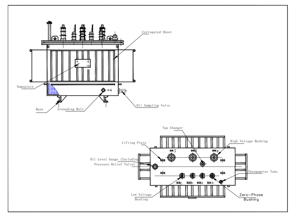
10kV High Overload Oil-Immersed Transformer
| Rated Capacity | H.V. | L.V. | Connection symbol | No-load loss(w) | On-load loss(w) | Short circuit impedance | ||||
|---|---|---|---|---|---|---|---|---|---|---|
| S13 | S20 | S22 | S13 | S20 | S22 | |||||
| 30 | 6 6.3 10 10.5 11 |
0.4 | Dyn11 Yyn0 |
80 | 70 | 65 | 630/660 | 505/480 | 455/430 | 4 |
| 50 | 100 | 90 | 80 | 910/870 | 730/695 | 655/625 | ||||
| 63 | 110 | 100 | 90 | 1090/1040 | 870/830 | 785/745 | ||||
| 80 | 130 | 115 | 105 | 1310/1250 | 1050/1000 | 945/900 | ||||
| 100 | 150 | 135 | 120 | 1580/1500 | 1265/1200 | 1140/1080 | ||||
| 125 | 170 | 150 | 135 | 1890/1800 | 1510/1440 | 1360/1295 | ||||
| 160 | 200 | 180 | 160 | 2310/2200 | 1850/1760 | 1665/1585 | ||||
| 200 | 240 | 215 | 190 | 2730/2600 | 2185/2080 | 1970/1870 | ||||
| 250 | 290 | 260 | 230 | 3200/3050 | 2560/2440 | 2300/2195 | ||||
| 315 | 340 | 305 | 270 | 3830/3650 | 3065/2920 | 2760/2630 | ||||
| 400 | 410 | 370 | 330 | 4520/4300 | 3615/3440 | 3250/3095 | ||||
| 500 | 480 | 430 | 385 | 5410/5150 | 4330/4120 | 3900/3710 | ||||
| 630 | 570 | 510 | 460 | 6200 | 4960 | 4460 | 4.5 | |||
| 800 | 700 | 630 | 560 | 7500 | 6000 | 5400 | ||||
| 1000 | 830 | 745 | 665 | 10300 | 8240 | 7415 | ||||
| 1250 | 970 | 870 | 780 | 12000 | 9600 | 8640 | ||||
| 1600 | 1170 | 1050 | 940 | 14500 | 11600 | 10440 | ||||
| 2000 | 1360 | 1225 | 1085 | 18300 | 14640 | 13180 | 5 | |||
| 2500 | 1600 | 1440 | 1280 | 21200 | 14840 | 13360 | ||||
FAQ
1.What is the difference between a high-overload transformer and an ordinary transformer?
① The core difference lies in the design concept and capability.Ordinary transformer: Like a marathon runner, it is required to operate stably at its rated capacity for a long time, with weak overload capability. Short-term overload will cause severe overheating, leading to insulation aging or even damage.
② High-overload transformer: Like a heavyweight boxer, its “skeleton” (windings, core) and “muscles” (insulation system) are specially reinforced, enabling it to withstand 1.5-times or even 2-times the rated capacity for a short period (such as several hours) with “explosive force” without damaging itself or affecting its normal service life.
2.Will "overload" shorten the service life of the transformer?
This is a key misunderstanding. Properly designed and used overload will not significantly shorten the service life. High-overload transformers use high heat-resistance class insulation materials such as Class H (180℃) or Class C (220℃). Their design allows the winding hot-spot temperature to temporarily reach a very high value (such as 160℃) during overload, and the aging rate of the insulation material is still very slow at this temperature. Ordinary transformers use Class A insulation (105℃), which will accelerate aging when the temperature exceeds this value. Therefore, high-overload transformers control “overload” within a reasonable range that their insulation materials can withstand.
3.Does my project need to use a high-overload transformer?
① It is very suitable if your electrical load has the following characteristics:Low annual average load rate (<40%), but extremely high short-term or seasonal loads.Loads with severe impact or periodic fluctuations (such as the start-up of arc furnaces, rolling mills, and electrolytic cells).
② Having capacity expansion expectations but wanting to save investment, replacing a large-capacity ordinary transformer that may be needed in the future with one high-overload transformer.Limited installation space, unable to accommodate a larger-capacity transformer.
4. How to select a suitable high-overload transformer? What are the main parameters to consider?
① The following points must be clarified during selection:Load curve: Clear overload multiple and duration (for example, needing to operate at 1.6-times load for 4 hours).
② Rated capacity: Selected based on normal load, not overload load.
③ Insulation heat resistance class: At least Class H, which is the basis for ensuring overload capability.
④ Cooling method: Oil-immersed (ONAN, good heat dissipation, strong overload capability) or dry-type (good fire resistance, suitable for indoor use).
⑤ Loss value: Pay attention to no-load loss (Po) and load loss (Pk), and select energy-saving products to reduce operating costs.
⑥ Protection class: Select the corresponding IP protection class according to the installation environment.
5. What are the most important monitoring indicators during the operation of a high-overload transformer?
It is necessary to monitor the winding temperature (through pre-embedded PT100 sensors) and the top oil temperature (for oil-immersed type) in real time. Ensure that the temperature is controlled within the limits specified by our company even during overload. At the same time, the load current should also be monitored to ensure that it does not exceed the predetermined overload curve.
6. What should be noted after the end of high-overload operation?
After the end of overload operation, the transformer is in a high-temperature state. It should continue to operate under no-load or light-load conditions for a period of time, and use its own cooling system (natural air cooling or oil circulation) to gradually reduce the temperature to a normal level, avoiding stress damage to the insulation material caused by rapid cooling and heating. For transformers with forced air cooling, the fans should be turned off with a delay.
7. Is its maintenance the same as that of ordinary transformers?
① The basic maintenance items are similar (such as checking fasteners, cleaning the shell, and measuring insulation resistance), but there are key focuses.
② Oil analysis (for oil-immersed type): Conduct regular oil chromatography analysis (DGA), because the high temperature during overload may accelerate the aging of insulation materials and generate certain characteristic gases, and DGA can effectively detect potential faults.
Why Choose us ?
Built to last, engineered to perform.
Kete Transformer is a key national-level manufacturer specializing in transformers, recognized as a “Contract-Honoring and Promise-Keeping” enterprise, a high-tech enterprise, and a national-level enterprise technology center. It is recommended in the national directory for rural and urban power grid construction and renovation, as well as a recommended supplier of major electromechanical equipment for hydropower projects. Its products have been awarded the title of “National Quality Inspection Qualified Product – Quality Trustworthy Product” and “Nationally Recognized Product for Mechanical Industry Users.
Our Project
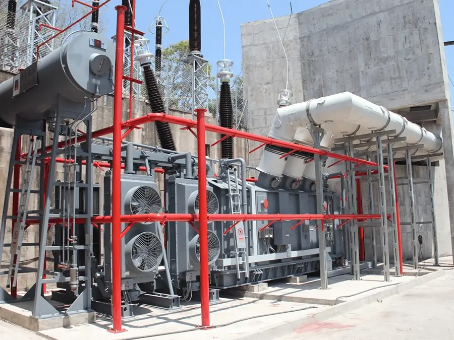
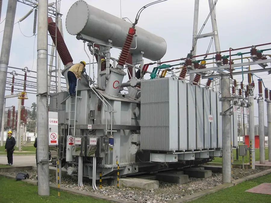
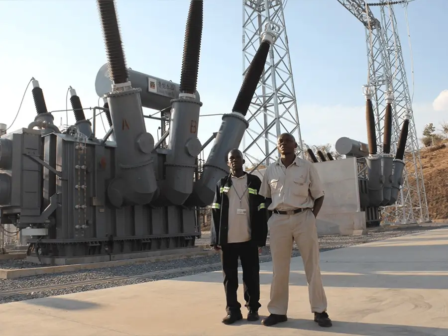
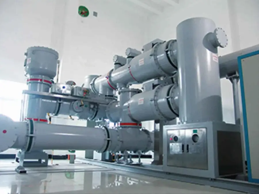
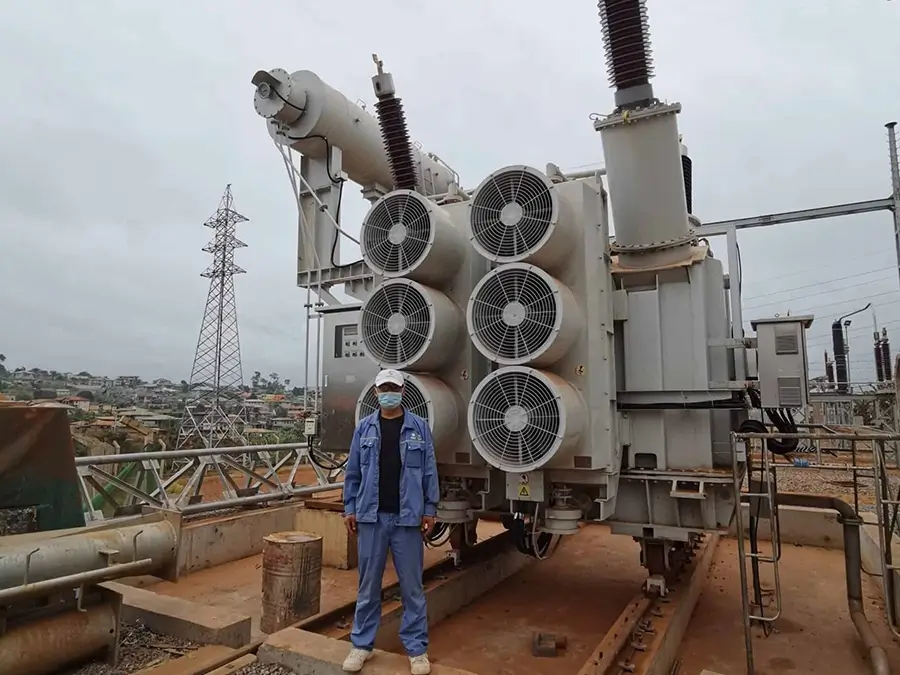
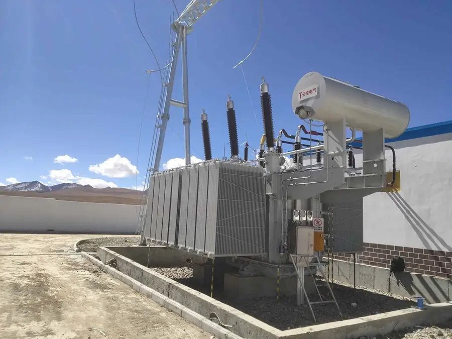
Our products not only dominate the domestic market but are also exported to more than 30 countries and regions, including Russia, Southeast Asia, Africa, and the Americas, serving industries such as power, municipal engineering, metallurgy, and petrochemicals.