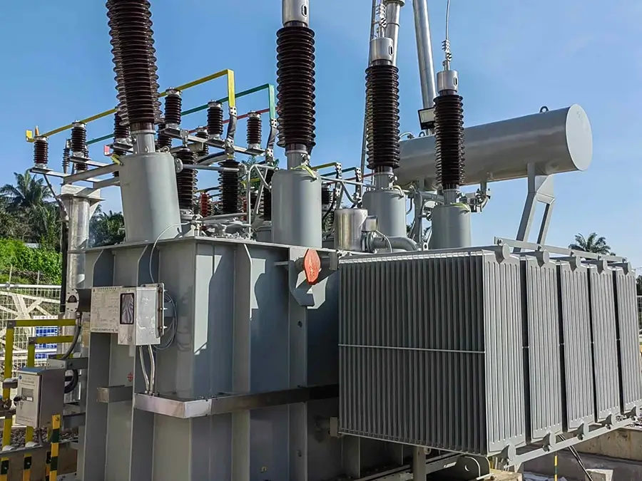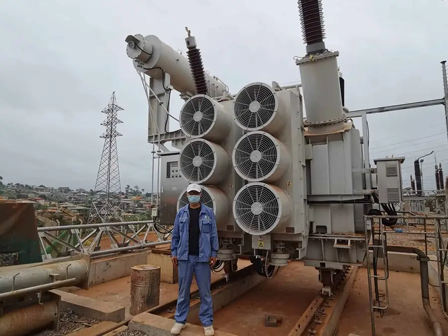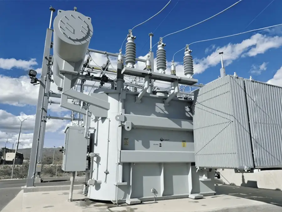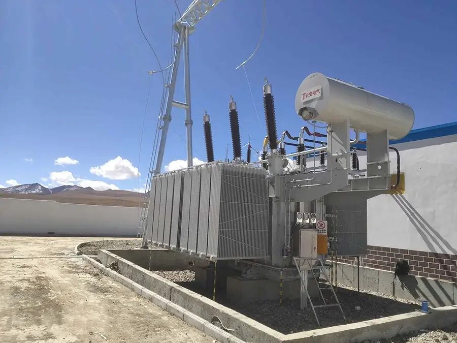






10kV SZ11 On-load Tap-changing Distribution Transformer
Overview
An on-load tap-changing transformer is a power transformer equipped with an on-load tap changer, which can adjust the tap positions under load conditions to maintain the stability of the output voltage. This transformer complies with the standards of GB1094 and GB/T6451. Thanks to the upgrading of materials, processes, structures and other aspects, its electrical performance has reached the advanced level in the global industry.
Brief introduction
Ⅰ.Brief introduction
1.Standards: IEC 60076, GB/T 1094, GB/T 25446-2010
2.Power Rating: 200KVA-2500 kVA
3.Primary Voltage: 10KV
4.Secondary Voltage: 0.4 kV or as required
5.Voltage regulation mode: On-load tap-changing
6.Frequency: 50HZ or 60HZ
7.Type: 3 Phase Electric Power Transformer
8.Connection Type: Dyn11, Yyn0, or per client specification
9.insulation grade:A
10.Cooling method: ONAN
Ⅱ.Working conditions
1.Ambient Temperature: No more than +40℃ No less than -25℃, The monthly average temperature is no more than +30℃, The yearly average temperature is no more than +20℃
2.Altitude: No more than 1000m.
3.Relative air humidity:≤90%
4.installation site: Clean and stable environment, compliance with safe distance requirements, sufficient heat dissipation and ventilation
5.Scope of application: On-load tap-changing transformers are widely used in fields such as power transmission, distribution systems, and renewable energy. In long-distance power transmission, they can adjust voltage to ensure power stability; in urban or industrial power distribution networks, they can automatically regulate voltage according to load changes; when renewable energy sources like wind and solar energy are connected to the power grid, they can quickly respond to grid changes and guarantee the stable supply of electricity.
Ⅲ.The tests for on-load tap-changing transformer
1.Factory Tests (Basic Verification During Manufacturing)
Factory tests are mandatory tests that must be completed before the transformer leaves the factory. They are used to ensure that the product meets design standards and technical agreements, mainly including:
①Insulation tests: Insulation resistance measurement, dielectric loss factor (tanδ)
②measurement, applied voltage withstand test, induced voltage withstand test.
③Winding DC resistance measurement.
④Transformation ratio test.
⑤Connection group test.
Special tests for on-load tap-changers: Mechanical operation test, transition resistance measurement, switching time measurement.
2.Type Tests (Comprehensive Performance Assessment for New Products or Major Improvements)
①Temperature rise test.
②Short-circuit withstand capability test.
③Lightning impulse test.
④Operating impulse test.
⑤Sound level measurement.
⑥Zero-sequence impedance measurement.
3.On-Site Handover Tests (Verification Before Commissioning After Installation)
①Inspection of appearance and accessories.
②Insulation test.
③On-site operation test of on-load tap-changer.
④Oil quality test.
⑤Cooling system test.
4.Preventive Tests (Regular Maintenance and Detection During Operation)
①Insulating oil test.
②Measurement of winding insulation resistance and dielectric loss.
③Condition detection of on-load tap-changer.
④Mechanical characteristic test.
⑤Contact wear inspection.
⑥Core grounding current measurement.
⑦Infrared thermal imaging detection.
The special tests for on-load tap-changers (mechanical operation, transition resistance, switching characteristics) are the core test contents that distinguish them from ordinary transformers.
Ⅳ.On-load tap-changing transformer component inspection
On-load transformers (transformers with tap changers) are key equipment in power systems. Their component inspection must cover two core parts: the transformer itself and the on-load tap changer (OLTC), as well as inspections of auxiliary systems. The following is a detailed classification and explanation of component inspection contents:
1.Inspection of Core Components of the Transformer Body
The transformer body is the core of electrical energy conversion, and key components such as insulation, iron core, windings, and oil tank need to be focused on:
①Winding Inspection: Include DC resistance test, insulation resistance and absorption ratio / polarization index test, dielectric loss (tanδ) test, winding deformation test, partial discharge test
②Iron Core Inspection: Indlude Iron core insulation resistance test and iron core grounding current test
The iron core is the core of the magnetic circuit, and multiple grounding or insulation damage must be prevented.
③Oil Tank and Accessory Inspection: Include oil tank tightness inspection, oil conservator and oil level gauge inspection, bushing inspection
2.Special Inspection of On-Load Tap Changer (OLTC)
OLTC is the core component of on-load transformers, responsible for regulating voltage under load. Its inspection is directly related to the safe operation of the equipment:
①Mechanical Characteristic Inspection: include action sequence test, operating mechanism test, mechanical limit test
②Electrical Performance Inspection: Include contact resistance test, insulation resistance test, partial discharge test during switching, transition resistance test
③Oil Quality and Oil Chamber Inspection: Include OLTC insulation oil inspection and oil chamber tightness inspection
④Control and Protection System Inspection: Include control circuit test and protection function test
3.Inspection of Insulation Oil and Cooling System
①Insulation Oil Inspection: Include routine physical and chemical indicators and dissolved Gas Analysis in Oil (DGA)
②Cooling System Inspection: Include radiator/cooler inspection, temperature control system test
4.Inspection of Other Auxiliary Components
①Pressure relief valve inspection
②Gas relay (breather relay) inspection
③Grounding system inspection
The component inspection of on-load transformers must integrate four dimensions: electrical performance, mechanical characteristics, insulation status, and oil quality analysis. Focus should be placed on core components such as windings, iron cores, and OLTC, while covering auxiliary systems such as cooling, control, and protection. Through regular inspections (such as preventive tests and online monitoring), potential faults can be detected in a timely manner, ensuring the safe and stable operation of transformers.
Structural Features
Ⅰ.Product features
An on-load transformer (i.e., on-load tap-changing transformer) is a type of transformer capable of adjusting output voltage while operating under load. Its core feature revolves around “voltage regulation without power interruption,” combining the basic energy transfer function of a transformer with dynamic voltage adjustment capability.
1.Core Functional Characteristics: Dynamic Voltage Regulation Under Load
This is the fundamental difference between on-load transformers and ordinary off-load tap-changing transformers, specifically manifested as:
①Continuity and Flexibility of Voltage Regulation
The turns ratio of the primary and secondary coils can be changed via the operating mechanism without disconnecting the load, enabling smooth adjustment of output voltage.
②Uninterrupted Energy Transfer
During voltage regulation, the transfer of current between different tap positions is achieved through the switching device of the on-load tap changer (e.g., transition resistors, reactors), ensuring continuous current flow in the primary and secondary coils and uninterrupted power supply to the load.
2.Structural Design Characteristics: Special Tap Changers and Protection Mechanisms
The core additional structure of an on-load transformer is the on-load tap changer, whose design directly affects the transformer’s reliability:
①Dual-Group Structure of On-Load Tap Changers
Tap changers typically consist of two parts: a selector switch and a diverter switch. The selector switch pre-selects the target tap position, while the diverter switch completes the current transfer from the current tap to the target tap under load. This dual-group structure reduces arcing and energy loss during switching.
②Transition Circuit and Arc-Quenching Design
During switching, transition resistors or reactors are connected to the circuit to limit short-circuit current and switching overvoltage. Meanwhile, vacuum interrupters or oil-immersed arc-quenching structures are used to quickly extinguish arcs generated during switching, preventing contact burnout and extending the switch’s service life.
③Mechanical and Electrical Protection Devices
Equipped with mechanical limiters, electrical interlocks (e.g., to prevent misoperation under load), overload protection, and gas protection (for oil-immersed types). In case of tap changer jamming, overload, or insulation failure, these devices automatically cut off the operating power and issue an alarm to ensure safe operation.
3.Operational Performance Characteristics: Efficiency, Stability, and Response Speed.
①Efficiency and Loss Characteristics
During normal operation, its efficiency is comparable to ordinary transformers (95%~99% or higher). However, the tap changer switching process generates minor additional losses (e.g., transition resistor loss, arc loss). These losses are negligible for overall efficiency due to their extremely short duration (millisecond level).
②High Voltage Regulation Precision
It can stably output voltage across the load range (from no-load to rated load) with a regulation precision typically reaching ±0.5%~±1%, meeting the high voltage stability requirements of precision equipment and industrial production lines.
③Fast Dynamic Response
The tap changer operates quickly (usually completing switching within seconds after receiving a voltage regulation command), enabling rapid response to grid voltage fluctuations (e.g., sudden load changes, line voltage drop variations) and preventing excessive voltage deviations from damaging equipment.
④Short-Circuit and Overload Withstand Capacity
The main body is designed to withstand short circuits like ordinary transformers. The tap changer must pass short-circuit current tests to ensure it remains undamaged during sudden short circuits. It also has a certain overload capacity (e.g., short-term overload of 1.2~1.5 times the rated current) to adapt to grid load fluctuations.
4.Application Scenario Characteristics: Adapting to Grid and Load Requirements
①Grid Voltage Regulation and Stabilization
Widely used in transmission and distribution links of power systems: At the transmission end, it compensates for line voltage drops to ensure qualified voltage at the end of long-distance transmission. At the distribution end, it adjusts voltage according to user-side load changes (e.g., peak-valley load differences) to prevent overvoltage or undervoltage.
②Adaptation to Industrial and Special Loads
Suitable for voltage-sensitive industrial loads (e.g., precision machine tools, electronic production lines, large motor startups), ensuring stable equipment operation through dynamic voltage regulation. It is also used in new energy power generation systems (e.g., wind, photovoltaic) to compensate for voltage fluctuations during grid connection and improve grid compatibility.
③Maintenance and Lifespan Characteristics
The tap changer is a vulnerable component requiring regular maintenance (e.g., cleaning contacts, replacing insulating oil, inspecting transition resistors), with a maintenance cycle typically of 1~3 years and higher maintenance costs than ordinary transformers. However, its overall service life is comparable to ordinary transformers (20~30 years), and proper maintenance can extend its operational cycle.
The core characteristics of on-load transformers can be summarized as: on-load voltage regulation without interruption, precise regulation with fast response, complex structure requiring maintenance, and adaptation to grids and sensitive loads. Through the special design of tap changers, they achieve the core function of “voltage regulation without power interruption,” serving as key equipment for voltage stability control in power systems and power supply for complex loads. Regular maintenance is essential to ensure the reliability of tap changers.
Ⅱ.Product Advantages
The core advantage of on-load transformers lies in addressing the pain point of traditional off-load transformers, which require power outage during voltage regulation. Here are their main advantages:
1.Ensuring Power Supply Continuity and Improving Reliability
①Voltage regulation without power outage: Unlike traditional off-load transformers, which require disconnecting loads and cutting off power supply when adjusting voltage, on-load transformers can switch tap positions during load operation through the special design of on-load tap changers (such as transition resistors and vacuum arc-extinguishing structures), avoiding power outage accidents caused by voltage regulation.
②Reducing losses from power interruptions: For places with extremely high requirements for power supply continuity, such as hospitals, data centers, and precision manufacturing industries, on-load transformers effectively reduce economic losses, equipment damage, or safety risks caused by power outages.
2.Precise and Stable Voltage, Optimizing Power Quality
①Dynamic voltage regulation: In power systems, grid voltage may deviate from the rated value due to load fluctuations (e.g., peak/valley electricity consumption), changes in line losses, or instability of new energy generation (wind power, photovoltaic). On-load transformers can quickly adjust tap positions based on real-time voltage monitoring data (switching time is usually within a few seconds) to stabilize the output voltage within the allowable range (general error ≤ ±2.5%).
②Adapting to complex load scenarios: In industrial production, voltage fluctuations caused by impact loads such as large motor startups and welding machine operations can be timely regulated by on-load transformers, ensuring normal equipment operation and reducing product quality issues or equipment failures caused by voltage instability.
3.Improving Grid Operation Efficiency and Economy
①Reducing line losses: When the voltage at the end of the grid is low, line current increases, leading to higher losses (losses are proportional to the square of current). By increasing the output voltage, on-load transformers reduce line current, decrease active power losses, and improve grid transmission efficiency.
②Extending equipment lifespan: A stable voltage environment reduces insulation aging and mechanical wear of electrical equipment (e.g., motors, transformers, capacitors), extending their service life and lowering maintenance costs and replacement frequency.
③Adapting to new energy grid-connection needs: New energy generation such as wind and photovoltaic power has volatility and intermittency, which can cause voltage fluctuations at grid-connection nodes. On-load transformers dynamically regulate voltage to ensure stable integration of new energy power into the grid and improve new energy absorption capacity.
4.Enhancing Grid Flexibility and Regulation Capability
①Flexibly responding to load changes: With urban development and industrial upgrading, the growth rate and distribution characteristics of power loads continue to change. On-load transformers can adapt to load demands in different regions and time periods through voltage regulation, optimize grid power distribution, and avoid overload or light-load operation of local grids.
②Supporting grid interconnection and upgrading: In multi-grid interconnection, old grid transformation, or smart grid construction, the dynamic voltage regulation function of on-load transformers improves grid coordination and compatibility, simplifies grid dispatching 难度,and enhances system stability.
5.Wide Application Scenarios and Strong Practicability
On-load transformers are not only applicable to high-voltage transmission networks and medium-voltage distribution systems but also to scenarios such as industrial enterprise self-owned power stations, rail transit power supply systems, and high-rise building distribution. Their voltage regulation range is usually wide (with multiple tap positions, such as ±3×2.5%, ±5×1.25%, etc.), which can meet the needs of different voltage levels and regulation accuracies, making them highly versatile and practical.
Through core advantages such as non-outage voltage regulation, precise voltage stabilization, loss reduction and efficiency improvement, and flexible regulation, on-load transformers significantly enhance the reliability, economy, and flexibility of power systems. They are indispensable key equipment in modern power networks, and their role becomes increasingly important especially in the context of growing demands for new energy grid-connection, smart grid construction, and high-quality power supply.
Product structure
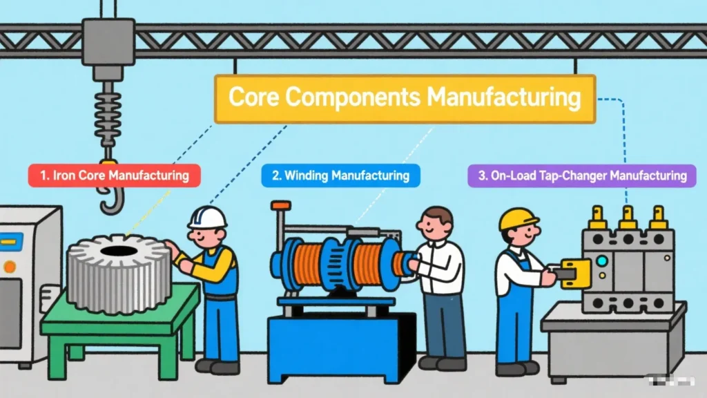
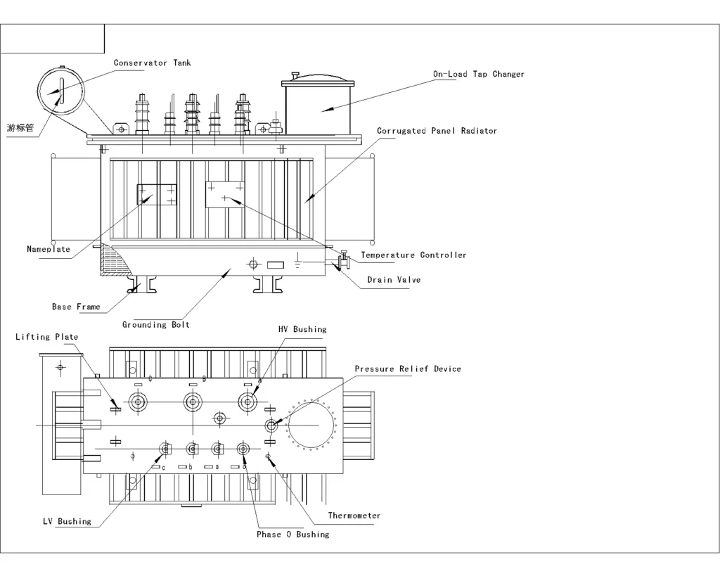
The core components of oil-immersed transformers include the iron core, windings, and oil tank. The manufacturing precision of these three components directly affects the performance of the transformer.
Ⅰ.Core Component Manufacturing
1.Iron Core Manufacturing
Silicon steel sheet cutting, iron core lamination, curing, and shaping.
2.Winding Manufacturing
Conductor processing, winding, and insulation treatment.
3.On-Load Tap-Changer Manufacturing
Processing of key components, assembly and debugging, insulation and sealing.
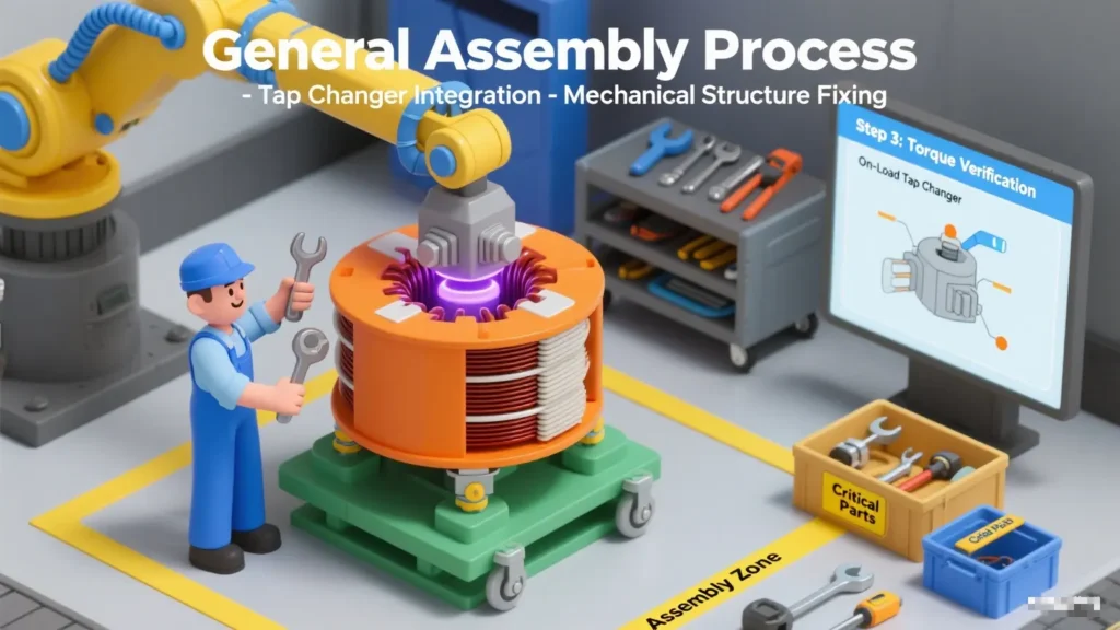
Ⅱ.Final Assembly
1.Assembly of the transformer body
2.Assembly of overall drying
3.Assembly of the oil tank.
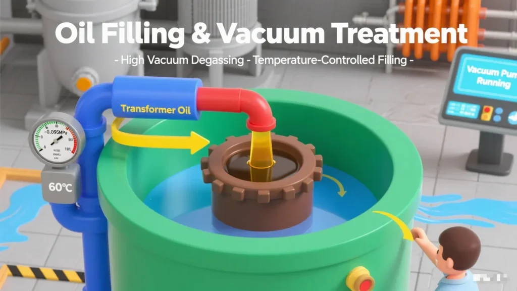
Ⅲ.Oil Filling and Vacuum Treatment
1.Vacuum oil filling,
2.Hot oil circulation.
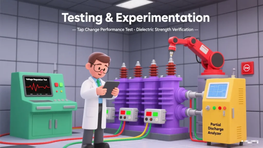
Ⅳ.Testing and Inspection
1.Routine tests
2.Special inspection of on-load tap-changers
3.Overall performance inspection.
Specification
10kV SZ11 On-load Tap-changing Distribution Transformer
| Rated Capacity | H.V. | High-Voltage Tap Range | L.V. | Connection symbol | No-load loss(kw) | On-load loss(kw) | No-Load Current% | Short circuit impedance% |
|---|---|---|---|---|---|---|---|---|
| 200 | 6 6.3 10 10.5 |
±4*2.5% | 0.4 | Dyn11 Yyn0 |
0.38 | 2.90 | 1.00 | 4 |
| 250 | 0.44 | 3.42 | 0.90 | |||||
| 315 | 0.53 | 4.10 | 0.90 | |||||
| 400 | 0.64 | 4.95 | 0.80 | |||||
| 500 | 0.76 | 6.89 | 0.80 | |||||
| 630 | 0.96 | 7.26 | 0.60 | 4.5 | ||||
| 800 | 1.12 | 8.89 | 0.60 | |||||
| 1000 | 1.36 | 10.40 | 0.60 | |||||
| 1250 | 1.56 | 12.30 | 0.50 | |||||
| 1600 | 1.92 | 14.70 | 0.50 | |||||
| 2000 | 2.27 | 18.60 | 0.40 | 5 | ||||
| 2500 | 2.68 | 21.60 | 0.40 |
FAQs
Ⅰ.Basic Maintenance Service
1.What are the rated voltage and power of the Kete oil-immersed OLTC transformer?
①Primary Voltage (High Voltage Side): Typically range from 1 kV to 66 kV, with common ratings like 6kV, 10 kV, 11KV, 20KV, 33 kV, 34.5KV, 35KV
②Secondary Voltage (Low Voltage Side): Common secondary voltage ratings include:
·400 V (0.4 kV) for industrial and residential supply
·11 kV or 33 kV
③Customization: Transformers can be designed for specific applications. If you have specific power requirements or voltage needs, we can specially design and customize transformers to meet your demands.
2.What type of cooling system does the Kete oil-immersed OLTC transformer use?
Kete oil-immersed OLTC transformers mainly adopt two common cooling methods: ONAN and ONAF.
①Scope of Application of ONAN
·Transformers with small capacity
Typical applicable capacity: Usually used for transformers of 10kV class with 500kVA and below, and 35kV class with 1000kVA and below.
Reason: Small-capacity transformers have low losses (small heat generation), and natural heat dissipation can meet the temperature rise requirements, with a simple structure and low cost.
·Scenarios with loose installation environment
Suitable for outdoor open spaces, well-ventilated indoor distribution rooms, or areas with low ambient temperatures.
If installed in enclosed spaces (such as basements), additional evaluation of heat dissipation conditions is required, and the cooling method may need to be upgraded.
·Transformers with low load rate or intermittent operation
For transformers that are in a light load state for a long time (load rate < 50%), the heat dissipation capacity of ONAN is sufficient, without wasting energy consumption from forced cooling.
②Scope of Application of ONAF
·Medium and large capacity transformers
Typical applicable capacity: 10kV class with 800kVA and above, 35kV class with 1600kVA and above for small and medium-sized transformers.
Reason: Medium and large-capacity transformers have high losses (large copper loss and iron loss), and natural heat dissipation cannot meet the temperature rise limit, so fans are needed to assist in enhancing heat dissipation.
·Transformers with high load rate or continuous operation
Suitable for scenarios with long-term full-load operation or large load fluctuations (needing to cope with short-term overload), such as main transformers in industrial plants and hub transformers in urban distribution networks.
·Environments with limited heat dissipation conditions
If the transformer is installed in a poorly ventilated indoor environment or in areas with high ambient temperatures (such as tropical regions), ONAF can make up for the deficiency of natural heat dissipation through forced air cooling, avoiding excessive oil temperature that affects service life.
3.How does the cooling system of the Kete oil-immersed OLTC transformer affect its performance under different climatic conditions?
The impact of ONAN (Oil-Immersed Natural Air Cooling) and ONAF (Oil-Immersed Forced Air Cooling) cooling systems of Kete oil-immersed OLTC transformers on performance under different climatic conditions is as follows:
①Impact of High-Temperature Climate
·ONAN Cooling System: When the ambient temperature exceeds 40°C, the heat dissipation efficiency of the ONAN cooling system decreases significantly, potentially dropping to approximately 60%. This is because high temperatures reduce the viscosity of the oil, weakening its fluidity and thus lowering the efficiency of natural convection heat dissipation. At this point, the winding temperature of the transformer rises rapidly, accelerating insulation aging. According to the Arrhenius law, the insulation life is halved for every 8°C increase in temperature. Meanwhile, high temperatures cause a decrease in the magnetic permeability of silicon steel sheets and an increase in eddy current losses, reducing energy efficiency. The transformer may need to be derated; otherwise, there are risks of insulation damage and fire.
·ONAF Cooling System: In high-temperature environments, the cooling effect of the fans in the ONAF cooling system diminishes. Although heat dissipation can be enhanced by adding auxiliary cooling equipment, the overall performance is still affected to a certain extent. However, compared to the ONAN cooling system, the ONAF system, with active heat dissipation by fans, achieves higher heat dissipation efficiency under the same high-temperature conditions. It can better control the transformer’s winding temperature and delay insulation aging.
②Impact of Low-Temperature Climate
·ONAN Cooling System: In low-temperature environments, such as temperatures below -30°C, the viscosity of transformer oil increases sharply, leading to greater circulation resistance. This may cause heat dissipation to stagnate, or even result in oil solidification (the pour point of transformer oil is approximately -45°C). In addition, dissolved water in the oil may turn into suspended ice crystals, increasing the risk of partial discharge. During cold startup, mechanical stress may cause welds or insulation to crack due to brittleness. Therefore, in extremely low temperatures, preheating to above 0°C is required before commissioning.
·ONAF Cooling System: In low-temperature environments, apart from the issue of increased oil viscosity similar to that of ONAN, the ONAF cooling system also faces the risk of fan icing. This can affect the normal operation of the fans and further impair heat dissipation efficiency.
③Impact of High-Humidity and Salt-Spray Climate
·ONAN Cooling System: In high-humidity environments with humidity exceeding 90%, the moisture content of insulation paper increases, causing the dielectric strength to decrease by approximately 30% and reducing the transformer’s insulation performance. In salt-spray environments, winding joints are corroded, increasing contact resistance and leading to local overheating, which affects the transformer’s normal operation and service life.
·ONAF Cooling System: High-humidity and salt-spray climates affect the ONAF cooling system similarly to ONAN, mainly causing insulation performance degradation and component corrosion. However, since the ONAF cooling system is equipped with rotating components such as fans, in high-humidity environments, additional attention must be paid to preventing issues such as moisture-induced short circuits in fan motors.
4.What is the main basis for choosing between ONAN and ONAF cooling methods for kete oil-immersed OLTC transformers?
The choice between ONAN (Oil Natural Circulation and Air Natural Cooling) and ONAF (Oil Natural Circulation and Air Forced Cooling) cooling methods for Kete oil-immersed OLTC transformers is corely based on the matching between the transformer’s heat dissipation requirements and actual heat dissipation conditions. Specifically, it can be comprehensively judged from the following 5 key dimensions:
①Transformer Rated Capacity and Heat Generation from Losses
This is the most fundamental basis. The heat generated by a transformer mainly comes from copper losses (load losses) and iron losses (no-load losses). The larger the capacity, the higher the losses and the stronger the heat dissipation demand:
·Small-capacity transformers (low loss):
When the rated capacity is small (e.g., ≤500kVA for 10kV class, ≤1000kVA for 35kV class), the heat generated by losses is small. Heat can be dissipated through the natural convection of transformer oil (hot oil rises, cold oil falls) and the natural convection between the casing/radiator and air, without the need for additional cooling equipment. Therefore, ONAN is preferred.
·Medium and large-capacity transformers (high loss):
When the capacity exceeds the above range (e.g., ≥800kVA for 10kV class, ≥1600kVA for 35kV class), losses increase significantly, and the natural heat dissipation rate cannot match the heat generation. This may cause the oil temperature to exceed national standard limits (usually top oil temperature rise ≤55K or 60K). In such cases, fans must be used to force air flow and accelerate heat dissipation, so ONAF is chosen.
②Operating Load Characteristics
The actual load rate and operation mode of the transformer directly affect heat dissipation requirements:
·Low load rate or intermittent operation:
If the transformer operates at light load for a long time (load rate < 50%) or only runs during short-term peak periods (e.g., rural distribution transformers), even if its capacity is slightly larger, the actual heat generation is low. The natural heat dissipation capacity of ONAN can meet the demand, and there is no need to waste energy on fans. Thus, ONAN is selected.
·High load rate or continuous full-load operation:
For transformers in industrial parks, urban core distribution networks, and other equipment that operate at full load for a long time or have large load fluctuations (needing to cope with short-term overload), heat generation remains high. ONAN cannot meet the heat dissipation requirements, so ONAF’s forced air cooling via fans is necessary. Even during overload, fans can enhance heat dissipation capacity (usually supporting 10%-20% short-term overload). Hence, ONAF is chosen.
③Installation Environment and Heat Dissipation Conditions
Environmental factors directly affect the efficiency of natural heat dissipation, and cooling methods need to be adjusted according to scenarios:
·Well-ventilated and low-temperature environments:
If the transformer is installed in an open outdoor area, high-altitude regions (low air density but good ventilation), or cold areas, the efficiency of natural convection heat dissipation is high. Even if the capacity is close to the critical value, ONAN can be prioritized.
·Poorly ventilated and high-temperature environments:
If installed in enclosed distribution rooms, basements, tropical regions, or industrial environments with heavy dust/oil pollution, natural heat dissipation is hindered. Even with a slightly smaller capacity, oil temperature may rise excessively due to poor heat dissipation conditions. In such cases, upgrading to ONAF is necessary to compensate for environmental defects through forced air flow by fans.
④Cost and Maintenance Requirements
There are significant differences in initial costs and operation/maintenance costs between the two cooling methods:
·Advantages of ONAN:
It has no fans or control circuits, resulting in a simpler structure. The initial procurement cost is low (5%-10% lower than ONAF of the same capacity), and there is no need for motor maintenance, making long-term operation and maintenance costs almost zero. It is suitable for scenarios sensitive to cost and with limited maintenance resources (e.g., rural power grids, small user transformers).
·Disadvantages and necessity of ONAF:
It requires additional configuration of fans, thermostats, and power circuits, leading to higher initial costs. Fan motors need regular inspection (dust cleaning, bearing lubrication), involving certain maintenance workload and energy consumption (fan power is usually tens to hundreds of watts). However, for medium and large-capacity transformers or those with insufficient heat dissipation conditions, these costs must be borne to ensure safe operation. Thus, ONAF is a “necessary choice” rather than a “cost-priority choice.”
5.How long is the service life of Kete oil-immersed OLTC transformers?
According to international standards (such as IEC 60076), the design life of Kete oil-immersed OLTC transformers is usually calculated as 20 years. This is the expected service life under the ideal condition of “normal operating conditions + regular maintenance”, which refers to the time it takes for core components (iron core, windings, insulating oil) to age to a critical state within the design parameters.
Practical industry reference range: In actual power grid or industrial applications, it is a dynamic indicator affected by multiple factors such as design standards, operating conditions, and maintenance levels. The service life of transformers can generally reach 20-40 years.
6.What are the factors that affect the service life of Kete OLTC oil-immersed transformers?
The service life of on-load tap-changer (OLTC) transformers is determined by the combined effects of multiple factors across design, operation, maintenance, and other stages. The core influencing factors can be categorized into four major types: equipment quality itself, operating conditions, maintenance management, and external environment.
①Equipment Quality Factors (Inherent Foundation of Service Life)
The design, materials, and manufacturing processes of the equipment at the factory directly determine its “inherent upper limit of service life”. The core influencing components and associated issues are as follows:
·Quality of the On-Load Tap-Changer (OLTC)
The OLTC is the core component of an OLTC transformer (enabling voltage regulation under load), and its quality defects are the primary inherent factor leading to shortened service life:
Contact Material: If ordinary copper alloys are used instead of silver alloys/copper-tungsten alloys (which offer high conductivity and wear resistance), the contact wear rate will accelerate, contact resistance will increase, and long-term overheating will cause ablation.
Insulation Structure: If there are bubbles or impurities in insulation cylinders or insulation oil channels, or if the temperature resistance level of insulation materials (e.g., epoxy resin) is insufficient (below the 105°C standard for Class A insulation), breakdown is likely to occur during operation, triggering partial discharge.
Sealing Performance: If the machining accuracy of OLTC sealing surfaces (e.g., flanges, shaft seals) is insufficient, insulation oil leakage will occur, allowing moisture and impurities to enter and accelerating insulation aging.
·Quality of Iron Core and Windings
Iron Core Silicon Steel Sheets: Excessive gaps between stacked silicon steel sheets or damaged insulation coatings will increase iron loss (eddy current loss and hysteresis loss), leading to long-term overheating of the iron core and accelerated aging of insulation paint.
Winding Conductors and Insulation: Uneven cross-sections or insufficiently soldered joints of conductors will result in excessively high local current density.
Insulation paper (e.g., cable paper, crepe paper) with low fiber density and poor aging resistance will quickly become brittle at high temperatures, shortening the insulation life of windings.
·Quality of Insulation Oil
If insulation oil is not subjected to strict degassing, dehydration, and impurity removal processes at the factory (e.g., excessive dielectric loss, breakdown voltage lower than 35kV/2.5mm), the overall insulation performance will be directly reduced, creating hidden risks of partial discharge and winding breakdown during operation.
②Operating Condition Factors (Acquired Accelerators of Life Loss)
If operating parameters such as load, voltage, and temperature exceed the design range, equipment aging will be significantly accelerated—making these the core acquired factors affecting service life:
·Long-Term Overload Operation
When the load factor exceeds the rated value (e.g., long-term operation above 120%), the winding copper loss (P=I²R) increases with the square of the current, causing a sharp rise in winding temperature:
If the winding temperature exceeds the 105°C upper limit allowed for Class A insulation (with hot-spot temperatures even reaching 120°C or higher), the degree of polymerization of insulation paper will decrease rapidly (by approximately 50–100 per year), potentially shortening the normal service life (20–30 years) to less than 10 years.
Overload also increases the current through OLTC contacts, intensifying arc ablation and doubling contact wear.
·Impact of Voltage Deviation and Harmonics
Long-Term Overvoltage: If the system voltage is more than 5% higher than the rated value, the iron core magnetic flux density will saturate, increasing iron loss and causing iron core overheating. At the same time, the electric field strength borne by winding insulation will rise, accelerating insulation aging.
Harmonic Pollution: Harmonic currents (e.g., 3rd, 5th harmonics) increase additional winding losses and iron core losses, leading to local overheating. Meanwhile, harmonic voltages exacerbate the electrical aging of insulation (e.g., increased partial discharge).
·Tap-Changing Frequency and Method
Frequent Tap-Changing: If tap-changing is performed more than 20 times per day, OLTC contacts will frequently connect/disconnect current. Each operation generates an arc, accelerating contact wear (the normal service life of contacts is approximately 100,000 operations, which can be shortened to less than 30,000 operations with frequent use).
Load Fluctuations During Tap-Changing: Sudden load surges (e.g., motor startup) during tap-changing can cause poor contact between contacts, generating “spark discharge” and further damaging contacts and insulation.
·Temperature and Temperature Difference Shock
Excessively High Ambient Temperature: For outdoor transformers in summer, if the ambient temperature exceeds 40°C, the top oil temperature of the transformer will rise (exceeding the allowable 85°C), accelerating the oxidation rate of insulation oil (the oxidation rate doubles for every 10°C increase in temperature) and worsening oil quality.
Excessive Day-Night Temperature Difference: In northern China during spring and autumn, if the day-night temperature difference exceeds 20°C, thermal expansion and contraction of components such as the oil tank and bushings will occur, creating micro-gaps on sealing surfaces and causing insulation oil leakage and moisture intrusion.
③Maintenance Management Factors (Determining Whether Service Life Meets Standards)
Lack of scientific maintenance accelerates equipment deterioration and is a key human factor leading to shortened service life:
·Inadequate Maintenance of Insulation Oil
Infrequent Oil Quality Testing: Failure to test insulation oil properties (e.g., dielectric loss, breakdown voltage, moisture content) every 6 months in accordance with standards will result in undetected oil deterioration (e.g., increased acid value, sludge formation), leading to a continuous decline in insulation performance.
Delayed Oil Replacement/ Filtration: When oil quality exceeds standard limits (e.g., moisture content > 30ppm), failure to perform vacuum oil filtration or oil replacement will contaminate winding insulation with impurities in the oil, intensifying partial discharge.
·Insufficient OLTC Maintenance
Infrequent Contact Inspection: Failure to disassemble and inspect OLTC contact wear every 2–3 years will allow contacts with excessive wear to continue operating, increasing contact resistance and causing long-term overheating and ablation.
Failure to Replace Arc-Quenching Medium: If arc-quenching chambers of the OLTC (e.g., vacuum arc-quenching chambers, oil-immersed arc-quenching chambers) are not replaced according to their service life (approximately 20 years for vacuum arc-quenching chambers), arc-quenching capacity will decrease. Arcs cannot be extinguished quickly during tap-changing, leading to contact ablation.
·Untreated Cooling System Failures
Radiator Blockage: Failure to regularly clean dust and oil stains from radiator surfaces (once per quarter) reduces heat dissipation efficiency, increasing the top oil temperature by 5–10°C and accelerating insulation aging.
Fan/Oil Pump Malfunctions: For forced oil circulation air-cooled (OFAF) transformers, unprompted repairs of damaged fans or oil pumps result in loss of cooling capacity, causing a sudden rise in oil temperature in a short period and leading to insulation damage.
·Lack of Preventive Tests
Infrequent Insulation Tests: Failure to conduct winding DC resistance measurement, dielectric loss testing, and partial discharge detection every 1–2 years leaves hidden risks (e.g., inter-turn short circuits, insulation breakdown) undetected, ultimately leading to failures.
Unmonitored Iron Core Grounding Current: If the iron core grounding current exceeds 100mA (normally should be < 10mA) without treatment, local overheating of the iron core will occur, ablating the insulation paint.
④External Environment Factors (Catalysts for Accelerated Life Loss)
Pollutants, natural disasters, and other elements in the external environment directly erode equipment, accelerating aging:
·Contamination and Corrosion
Industrial Dust/Coastal Salt Spray: These substances adhere to bushing surfaces and form conductive paths in humid weather, causing bushing flashover discharge and damaging insulation. Salt spray also corrodes the metal casings of oil tanks and radiators, leading to leakage.
Chemical Corrosion: If there are chemical plants or printing and dyeing factories near the transformer, acidic and alkaline gases (e.g., SO₂, Cl₂) in the air will corrode insulation materials and metal components, shortening service life.
·Moisture and Humidity
In high-humidity environments (e.g., relative humidity > 85% during the plum rain season in southern China), moisture penetrates the equipment interior through sealing gaps, reducing the breakdown voltage of insulation oil (the breakdown voltage decreases by approximately 5kV for every 10ppm increase in moisture content) and accelerating rusting of the iron core and windings.
·Natural Disasters and External Impact
Lightning Strikes: Insufficient or faulty lightning arresters allow lightning overvoltage to break down winding insulation, causing inter-turn or phase-to-phase short circuits.
Earthquakes and External Collisions: These events cause iron core displacement and winding deformation, damaging the insulation structure. Even if no immediate failure occurs, hidden risks are left, accelerating life loss.
7.How to maintain transformers to maximize the service life of Kete OLTC oil-immersed amorphous alloy transformers?
To maximize the service life of on-load tap-changer (OLTC) transformers, a two-pronged approach of “innate control + acquired management” is required:
①Selection Stage: Prioritize high-quality equipment with OLTC contacts made of silver alloy, a high insulation class (e.g., Class A or above), and excellent sealing performance.
②Operation Stage: Control the load factor within 80%~100% of the rated value, avoid frequent tap changing, and monitor and suppress system harmonics.
③Maintenance Stage: Conduct regular inspections (in accordance with the DL/T 574-2010 standard) on oil quality, overhaul the OLTC, clean the cooling system, and ensure full coverage of preventive tests.
④Environmental Control: In polluted/high-humidity environments, install anti-pollution flashover coatings on bushings and moisture-proof covers for equipment, and improve the lightning protection and grounding system.
8.What aspects of Kete oil-immersed OLTC transformers can be customized?
As the core of on-load tap changing, the customization of voltage regulation parameters, modes, and voltage regulation control logic directly aligns with the voltage regulation requirements of power grids, and serves as the key direction for customization:
①Voltage Regulation Parameters and Modes
·Voltage Regulation Range: Customized according to the fluctuation range of the power grid.
·Voltage Regulation Speed: For high-frequency voltage regulation scenarios (such as photovoltaic/wind power plants), a “fast switching mode” is customized (switching time ≤ 0.5s); for conventional power grids, a “stable switching mode” is used.
·Tap Changer Type: Selected based on capacity and reliability requirements: “resistive type” (suitable for frequent voltage regulation with low impact) or “reactive type” (suitable for high capacity and high voltage, such as main transformers of 220kV and above).
②Voltage Regulation Control Logic
·Automatic Voltage Regulation: Customized with “voltage threshold triggering” (e.g., automatic voltage boosting when the voltage is lower than 10kV) and “load-linked voltage regulation” (dynamic adjustment based on load current to avoid overload);
·Protection Logic: Added with “tap position locking” (prohibiting voltage regulation in case of over-temperature/short circuit) and “fault self-recovery” (automatic rollback to a safe gear after switching failure).
Ⅱ.After-sales maintenance
1.What is included in Kete's warranty coverage during the warranty period? And how are the costs borne?
Our company’s warranty coverage includes performance failures caused by material defects or manufacturing process issues, such as cabinet water leakage, insulation failure, abnormal switch operation, etc.
We provide spare parts for maintenance free of charge, and will dispatch technical personnel for on-site inspection and repair if necessary, with travel expenses borne by the supplier.
2.Will Kete provide guidance documents for installation?
For large transformers that require the removal of some accessories to fit into containers, we will provide an installation video and an electronic version of the installation instructions.
3.If maintenance is required and spare parts are purchased from Kete, how long will it take for the spare parts to arrive?
If the customer needs to purchase spare parts from our company, the goods can generally be shipped within 2-7 days.
4.How to handle emergency maintenance requests, and what is the typical response time?
24/7 technical support hotline, ensuring a fault time of ≤ 2 hours.
5.What kind of after-sales support can Kete provide, including troubleshooting and maintenance services?
During the warranty period, regular return visits (once every 3 months) will be conducted to provide operation status testing and maintenance recommendations.
After the warranty period expires, lifelong maintenance services at cost price and spare parts supply can be provided.
6.Can Kete provide options for service contracts or extended warranty periods?
Yes, we can. Generally, the warranty period for our products is one year. If an extension of the warranty period is required, we will increase the price by a certain profit margin based on the existing price accordingly.
Ⅲ.Delivery and Payment
1.What is the manufacturing and delivery lead time for Kete oil-immersed transformers?
Generally speaking, if the customer provides detailed design drawings and specification requirements, transformers below 2500KVA can be completed within approximately 20 days; transformers above 2500KVA usually take about 30 to 40 days. The specific lead time depends on the complexity of the transformer.
2.What is the packaging for Kete oil-immersed amorphous alloy transformers?
For bulk cargo, we will use wooden cases for packaging; for full containers, we will use wooden pallets to reinforce the packaging.
If you have legally registered patent, we can pack the goods in your branded boxes after getting your authorization letters.
3.What are the payment terms for Kete transformers?
①T/T 30% as deposit, and 70% before delivery.
②LC at sight
③DP at sight
4.What are the delivery terms for the bulk shipment of Kete transformers?
EXW, FOB, CFR, CIF or some other delivery terms inquired by customers.
Ⅳ.Systems and Certifications
1.Does the design of Kete oil-immersed OLTC transformers comply with specific industry standards and certifications?
Kete Oil-Immersed Transformers Meet Various International Standards, National Standards, and Core Certification Systems
①General Standards: IEC 60076, GB 1094
②Key Certification Systems
·Chinese Certifications: CCC Certification, ISO System Certification
·EU Certification: CE Certification
·US Certification: UL Certification
·Canadian Certification: GSA Certification
·Russian Certification: Gost Certification
·African Certification: COC Certification
Why Choose us ?
Built to last, engineered to perform.
Kete Transformer is a key national-level manufacturer specializing in transformers, recognized as a “Contract-Honoring and Promise-Keeping” enterprise, a high-tech enterprise, and a national-level enterprise technology center. It is recommended in the national directory for rural and urban power grid construction and renovation, as well as a recommended supplier of major electromechanical equipment for hydropower projects. Its products have been awarded the title of “National Quality Inspection Qualified Product – Quality Trustworthy Product” and “Nationally Recognized Product for Mechanical Industry Users.
Our Project
Our products not only dominate the domestic market but are also exported to more than 30 countries and regions, including Russia, Southeast Asia, Africa, and the Americas, serving industries such as power, municipal engineering, metallurgy, and petrochemicals.