ZBW Combined Substation
Overview
ZBW Combined Substation is the core category of European box-type transformers. Based on European compact power distribution technology, it integrates high-voltage switchgear, power transformers, low-voltage distribution equipment, and protection, metering, and temperature control systems into a sealed box prefabricated in the factory. It only requires wiring on site before it can be put into use.
Brief Introduction
Ⅰ.Brief Intrucodtion
1.Customization:We offer highly customized ZBW Prefabricated Substation solutions. For example, compact designs can be customized for space-constrained urban areas, and specialized electromagnetic shielding can be employed for areas sensitive to electromagnetic interference.
2.Compliant Standards: IEC 62271-202, IEC 60076, IEC 61439, IEC 60076, EN 50522, EN 60439, EN 10169, EN 60947, GB/T 17467, ISO 12944, etc.
3.Voltage Levels:
①High-voltage side voltage levels include 6kV, 10kV, 20kV, and 35kV, suitable for power supply systems of varying sizes and types. Customization is supported, for example, 11/15/24kV.
②The low-voltage side voltage level is typically 0.4kV (400V/230V), suitable for directly powering various low-voltage electrical equipment, such as lighting, air conditioning, and small power equipment. This voltage level meets the needs of common electrical equipment in residential and general industrial sectors, ensuring safe and stable low-voltage power distribution. It is compatible with the European low-voltage distribution system.
4.Voltage Regulation Methods:
①Off-excitation voltage regulation: This method uses multiple taps installed on the transformer windings. During a transformer power outage, the number of turns is manually adjusted by adjusting the tap changer to achieve voltage regulation. This voltage regulation method is simple and low-cost, suitable for applications with minimal load fluctuations and low voltage regulation accuracy requirements, such as rural areas or locations with seasonal power consumption.
②On-load voltage regulation: This method uses an on-load tap changer to automatically or manually switch taps while the transformer is operating under load, achieving continuous voltage regulation. On-load voltage regulation (OLTC) quickly responds to load changes, adjusting output voltage in a timely manner to maintain voltage stability. It is suitable for applications with large load fluctuations and high voltage quality requirements, such as urban commercial centers and large factories, effectively ensuring the normal operation of various sensitive electrical equipment.
5.High-voltage tap range: Typically ±2 × 2.5% or ±5%. For example, a 10kV transformer with a ±2 × 2.5% tap adjustment allows for five tap levels: 9.5kV, 9.75kV, 10kV, 10.25kV, and 10.5kV, to accommodate grid voltage fluctuations.
6.Rated capacity: Rated capacity ranges from 30kVA to 2500kVA, meeting the power needs of users of varying sizes and supporting capacity expansion as load increases.
7.Other Information: This prefabricated substation uses three-phase power supply. Common connection groups are Dyn11 and Yyn0. The former is suitable for non-linear load scenarios, while the latter is suitable for applications with essentially balanced three-phase loads. Impedance voltage ranges from 4% to 8% and can be customized based on system and load characteristics. Cooling methods include oil-immersed natural cooling, oil-immersed air cooling, and dry air cooling, each suited to different loads and environmental conditions. Protection levels are generally IP33 and above, with higher levels customizable for specialized environments. Insulation grades include B (130°C), F (155°C), and H (180°C), selectable based on operating environment and load conditions.
Ⅱ.Operating Conditions:
1.Altitude: No more than 1000 meters
2.Ambient Temperature: -25°C to +40°C
3.Relative Humidity: Daily average not exceeding 95%, monthly average not exceeding 90%
4.Maximum Monthly Average Temperature: +35°C
5.Maximum Annual Average Temperature: +20°C
6.Minimum Ambient Temperature: 25°C (outdoor)
7.Maximum Diurnal Temperature Difference: 25°C
8.Sunlight Intensity: 0.1 W/cm² (0.5 m/s)
9.Seismic Resistance: EN 1998-1 (Horizontal Acceleration 0.3g)
10.Installation Location: Free from severe vibration, corrosive gases, explosive media, and heavy dust pollution
11.Applicable Areas:Widely applicable to urban power grid transformation, residential communities, industrial parks, commercial centers, municipal projects, and new energy projects (such as wind power and photovoltaic power generation).
Ⅲ.Test Types:
1.Type Tests: IEC 62271-200 (Internal Arc Test), IEC 60076 (Transformer)
2.Routine Tests: Loop Resistance, Power Frequency Withstand Voltage, Mechanical Operation, and Transformer Parameter Testing.
3.Special tests: Noise, EMC, high and low temperature/salt spray, and other environmental tests.
Ⅳ.Component Testing:
1.Transformer:Insulating oil withstand voltage (oil-operated transformer), partial discharge (dry-type transformer), temperature rise.
2.High-voltage components: Fuse characteristics, lightning arrester residual voltage.
3.Low-voltage units: Circuit breaker breaking capacity, busbar contact resistance.
4.Enclosure: Dust and water resistance (IP), mechanical strength (wind and vibration resistance).
Ⅴ.Certification Types:
1.International: IEC 62271-202, IEEE C57.12.00.
2.US: UL 1561 (dry-type transformer), UL C57.12.00 (oil-operated transformer).
3.China: GB/T 17467 (national standard), CQC certification. Other: CE (LVD/EMC), TÜV, UKCA (UK)
Structural Features
Ⅰ.Product Features:
1.Ultimate Safety and Environmental Protection
①Fireproof Design:
•Dry-type transformers (epoxy resin cast, IEC 60076-11) completely eliminate the risk of oil leakage and are certified to EN 13501-1 Class A1 fire protection.
•The high-voltage switchgear utilizes air-insulated technology (such as the ABB SafePlus series), eliminating SF6 greenhouse gas emissions and complying with EU F-Gas regulations.
①Electromagnetic Compatibility:
The fully shielded cabin design has passed stringent EMC testing according to EN 61000-6-2/-6-4, ensuring interference-free operation in sensitive environments such as hospitals and data centers.
2.Modular and Flexible Configuration:
①Separate compartment layout (high-voltage/transformer/low-voltage compartments):
•Back-to-back, in-line, and L-shaped arrangements are supported, making it suitable for narrow plots (with a minimum footprint of only 3m x 5m).
•Each module can be independently maintained, allowing for rapid fault isolation (MTTR ≤ 30 minutes).
②Intelligent Expansion:
•Pre-installed IEC 61850-8-1 communication interface for seamless integration into SCADA systems.
•20% busbar capacity reserved to support future PV/energy storage expansion.
Ⅱ. Product Advantages
1.Flexible Installation:The compartmented design allows for on-site assembly, shortening foundation construction by 30% and adapting to complex site conditions.
2.Reliable Operation:The oil-free dry-type transformer design reduces fire risk; the compartments offer excellent sealing performance, resisting dust and water, minimizing environmental interference.
3.Easy Maintenance: Each compartment features independent doors, and modular component installation allows for quick replacement, eliminating the need for total system downtime for routine maintenance.
Ⅲ. Product Benefits
1.Reduced Safety Costs: Enhanced protective design and interlocking devices reduce the risk of safety incidents, reducing annual safety investment by over 20%.
2.Fully Adaptable: Modular expansion capabilities can meet 10-15 years of load growth, avoiding redundant construction and optimizing total cost of ownership.
3.Low Operating Noise: Dry-type transformers with sound-absorbing design deliver a noise level of ≤55dB, making it suitable for noise-sensitive environments such as residential communities and hospitals.
ⅣEvidence
1.Certification and Testing: Certified by IEC 62271-202, CE, and GB/T 17467, the product has passed type testing to verify IP54 protection, internal arc resistance, and low-temperature operation stability at -25°C.
2.Application Cases: Data from European industrial parks and domestic commercial centers demonstrates a 40% reduction in installation cycles, a 10-year failure rate of less than 3%, and a 50% reduction in expansion and retrofit costs. A power grid company reported 200 units operating continuously for eight years without major failures.
3.Measured Data: A third-party test report indicates a short-circuit withstand capability of 31.5kA/3s, partial discharge ≤5pC, and noise ≤52dB (at a distance of 1 meter).
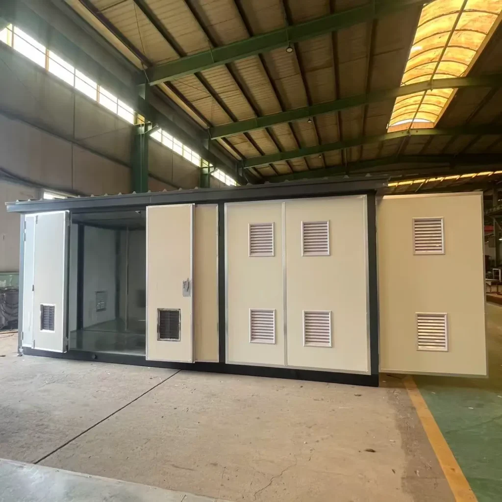
Product structure
The European-style combined substation (PFS) adopts a modular compartment design. It consists of three independent, sealed metal compartments (high-voltage compartment, transformer compartment, and low-voltage compartment), connected by bolts, ensuring both safety and scalability.
Ⅰ.Overall Structural Design
1. Design Standards
①Design Standards: Complies with IEC 62271-202 (prefabricated substation), EN 50427 (European), and GB/T 17467 (domestic).
②Seismic Resistance: Meets EN 1998 or user-specified regional seismic requirements.
③Protection Rating: IP54 for outdoor compartments, IP2X for internal switchgear compartments.
2. Modular Components
The European-style prefabricated cabin consists of three independent compartments:
①high-voltage compartment (for vacuum circuit breakers, disconnectors, etc.),
②transformer compartment (primarily dry-type transformers),
③low-voltage compartment (for drawer-type switchgear, smart metering, and reactive power compensation devices).
1. Cabin Structure
①Material:
•Shell: 304 stainless steel (thickness ≥ 2mm) or galvanized steel (anti-corrosion coating meets ISO 9227 salt spray test requirements for ≥ 1000h).
•Frame: Hot-dip galvanized steel beams (EN 10240), wind pressure resistance ≥ 1500Pa.
②Layout:
•Sub-cabin (three compartments arranged side by side or in a herringbone pattern), with a single compartment width ≤ 2.5m, making it easy to transport by road.
•The roof features a sloped design (slope ≥ 5°) to prevent water accumulation and is equipped with rainproof and ventilation louvers (with dust screens).
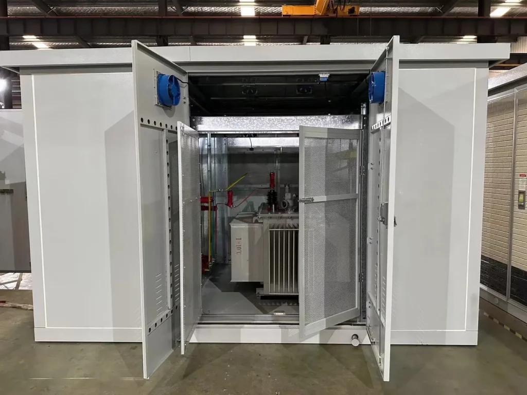
2. Transformer Compartment
Independent compartment equipped with:
①fireproof partitions (EN 13501-1 Class A1 fire resistance rating).
②Temperature control system (forced air cooling + temperature sensor, alarm threshold ≤ 100°C).
③Epoxy resin insulation (dry-type transformer) or explosion-proof oil tank (oil-immersed optional).
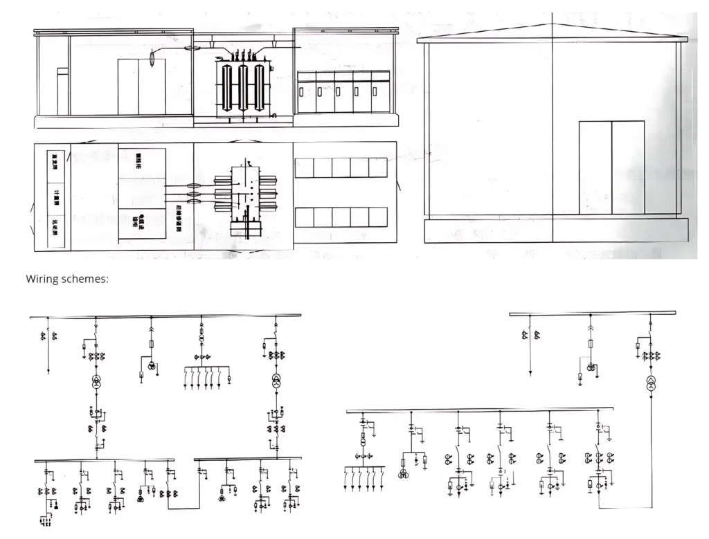
3. High and Low Voltage Equipment Layout
①High-voltage side: Vacuum circuit breakers (IEC 62271-100) or air-insulated ring main unit (RMU).
②Low-voltage side: Drawer-type switchgear (IEC 61439) + smart meter + reactive power compensation device.
③Busbar system: Copper busbars (IEC 61439), insulated and sheathed (temperature resistant ≥ 155°C).

Ⅲ. Special Structural Design
1. Modular Layout
①High-voltage compartment: Air-insulated switchgear (e.g., ABB SafeRing).
②Transformer compartment: Dry-type transformer (with temperature-controlled fan).
③Low-voltage compartment: Frame-mounted circuit breaker (e.g., Schneider Masterpact).
2. Special Design
①Fireproof partition: Ceramic silicone rubber (EN 13501-1 Class A1).
②Ventilation system: Top fan + bottom louvers (EN 60529).
③Intelligent: Supports IEC 61850 communication protocol.
3. Transportation and Installation Structure
①Lifting Points: Four lifting lugs are installed on the top of each compartment (load capacity ≥ 1.5 times the compartment weight).
②Foundation Requirements: Concrete platform (levelness ≤ 3 mm/m), pre-buried anchor bolts (EN 15048).
③Joint Design: Compartments are connected using flanges (sealing strips comply with ISO 3302-1) to ensure waterproofing.
Specification
ZBW Combined Substation
| Rated capacity(kVA) | High-voltage side voltage(kV) | Low-side voltage(V) | Number of phases | Cooling method | Protection level | Insulation grade | weight(kg) | Dimensions (mm) (L*W *H) |
|---|---|---|---|---|---|---|---|---|
| 50 | 6/10/35 | 400/230 | Three-phase | Dry air cooling | IP54 | F | 800 | 2500*1200*1800 |
| 200 | 6/10/35 | 400/230 | Three-phase | Dry air cooling | IP54 | F | 1500 | 3500*1500*2000 |
| 500 | 10/20/35 | 400/230 | Three-phase | Dry air cooling | IP54 | H | 2800 | 4500*1800*2200 |
| 1000 | 10/20/35 | 400/230 | Three-phase | Dry air cooling | IP54 | H | 4500 | 5500*2000*2500 |
| 2000 | 10/20/35 | 400/230 | Three-phase | Dry air cooling | IP54 | H | 6800 | 6500*2200*2800 |
FAQ
ZBW Combined Substation FAQ
When purchasing an ZBW Combined Substation, you may want to know the following questions & answers.
Ⅰ.Basic Concepts
1.What is a ZBW Prefabricated Substation?
This is an outdoor substation with a modular, compartmented design. It integrates high-voltage switchgear, transformers (primarily dry-type), and low-voltage distribution systems into three separate steel compartments. It complies with IEC and EN standards and is suitable for the European market and national standard projects.
2.How does it differ from American-style or traditional substations?
①European-style features:
Using vacuum circuit breakers or air-insulated ring main units, the three compartments are independent, providing high safety.
Transformers are mostly dry-type (compliant with IEC 60076) with an IP54 protection rating (outdoor use).
The cabin is primarily made of stainless steel, offering excellent corrosion and fire resistance.
②Comparison with American-style substations: The American-style substation features an integrated, compact design, primarily using oil-immersed transformers, and focuses on compatibility with North American standards.
Ⅱ. Technical Parameters
3. What are the standard voltage levels and capacity ranges?
①Voltage: 6-35kV (compliant with IEC 60038), customizable.
②Transformer capacity: 30kVA to 2500kVA (mainly dry type), oil-immersed type optional.
③Short-circuit withstand: 31.5kA/3s on the high-voltage side (IEC 62271-100).
4.What are the protection levels and corrosion resistance?
①Cab: IP54 (dust and water jet proof), with optional ISO 9227 salt spray test ≥1500 hours coating for corrosive environments.
②Internal equipment: Switchgear compartment IP2X (electric shock proof).
Ⅲ. Installation and Commissioning
5. What are the foundation requirements?
Concrete platform thickness ≥ 200mm, levelness ≤ 3mm/m, pre-buried anchor bolts (EN 15048).
Cable trench (width ≥ 600mm) and grounding grid (grounding resistance ≤ 4Ω) must be reserved.
6. Is on-site splicing required? What are the transportation restrictions?
①Sub-compartmental: Three compartments are shipped independently and bolted together on-site (flange connection + sealing strips for waterproofing).
②Single cabin size: Length ≤ 6m (road transport restrictions).
Why Choose us ?
Built to last, engineered to perform.
Kete Transformer is a key national-level manufacturer specializing in transformers, recognized as a “Contract-Honoring and Promise-Keeping” enterprise, a high-tech enterprise, and a national-level enterprise technology center. It is recommended in the national directory for rural and urban power grid construction and renovation, as well as a recommended supplier of major electromechanical equipment for hydropower projects. Its products have been awarded the title of “National Quality Inspection Qualified Product – Quality Trustworthy Product” and “Nationally Recognized Product for Mechanical Industry Users.
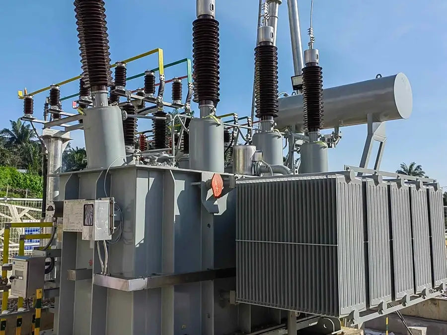
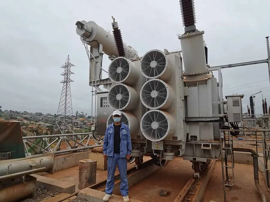
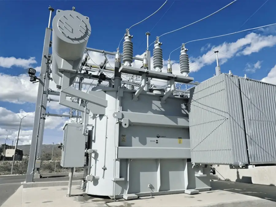
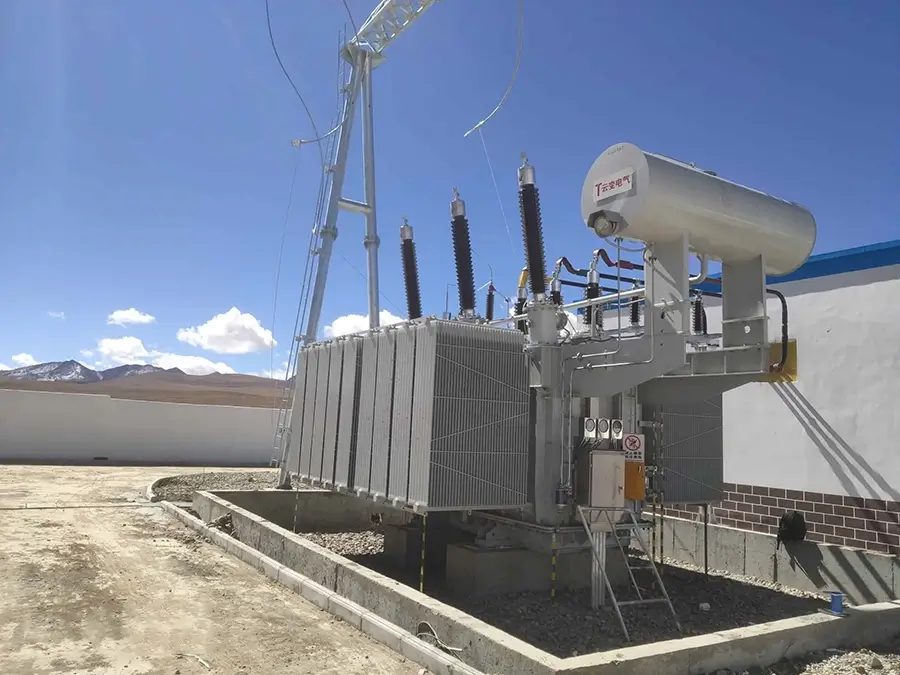
Our Project
Our products not only dominate the domestic market but are also exported to more than 30 countries and regions, including Russia, Southeast Asia, Africa, and the Americas, serving industries such as power, municipal engineering, metallurgy, and petrochemicals.