





6KV/10KV/13.8KV/15kV/ Pole Mounted Single Phase Circle Tank Shape Transformer
Overview
A pole-mounted transformer refers to a distribution transformer directly installed on overhead utility poles (electric poles). It is a key piece of equipment in the 10kV distribution network that converts high-voltage electrical energy into low-voltage electrical energy of 400V/230V for direct supply to users. Due to its installation location, it is also commonly known as a “pole transformer”.
Brief Introduction
Ⅰ. Product Introduction
1.Executive Standards: ANSI/IEC international standards.
2.Voltage Levels:
①Primary side voltage: Common values include 10kV, (10.5, 11, 6, 6.3, 6.6)kV, and some products can reach 36kV.
②Secondary side voltage: Common values are 0.22 (0.23, 0.24)kV, 0.4kV, etc.
3.Voltage Regulation Method: Most pole-mounted transformers adopt the off-circuit voltage regulation method, which means voltage adjustment is performed when the transformer is de-energized.
4.High-Voltage Tap Range: Typically ±2×2.5%. For example, for the high-voltage side of a 10kV transformer, the taps can be adjusted between 9.5kV and 10.5kV.
5.Rated Capacity: 3kVA – 800kVA.
6.Frequency: The rated frequency of pole-mounted transformers is 50Hz or 60Hz.
7.Phase Number: There are two types: single-phase and three-phase.
①Single-phase pole-mounted transformers are suitable for some low-voltage distribution scenarios.
②Three-phase pole-mounted transformers are more widely used and can meet the power demand of larger loads.
8.Connection Groups:
①The commonly used connection group for three-phase pole-mounted transformers is Dyn11. This connection method helps reduce third-harmonic currents and improve power supply quality.
②Single-phase transformers have a simple structure and do not use the “connection group” clock notation.
9.Impedance Voltage: The impedance voltage varies depending on the transformer’s capacity, generally around 4%. For example, pole-mounted transformers with a capacity of 100kVA or less usually have an impedance voltage of 4%.
10.Cooling Method: Mainly oil-immersed self-cooling, which dissipates heat through the natural circulation of insulating oil. Some products are also equipped with a circulating heat dissipation ring with high-efficiency heat dissipation fluid, and a composite heat dissipation channel formed by symmetrically distributed heat-conducting plates and semiconductor cooling chips to enhance heat dissipation effects.
11.Protection Level: In accordance with TCEC 111-2016 Technical Specifications for Integrated Complete Sets of Pole-Mounted Transformer Equipment, the enclosure protection level of high-voltage modules and low-voltage modules shall not be lower than IP44 to prevent the intrusion of foreign objects and splashing water.
12.Insulation Class: Usually Class A insulation. For oil-immersed transformers, the heat resistance class of their insulating materials is generally Class A, with a reference temperature of 75℃.
Ⅱ. Operating Conditions
1.Altitude: Areas with an altitude ≤1000m; some customized high-altitude products can meet higher requirements.
2.Climatic Parameters:
①Ambient temperature range: -30℃ ~ +40℃.
②Average maximum temperature in the hottest month: ≤35℃.
③Maximum wind speed: ≤30m/s.
④Solar radiation intensity: ≤0.1W/cm².
3.Pollution Level: Designed according to national standard Class C pollution areas, capable of withstanding moderate levels of industrial pollution and natural pollution.
4.Geological Conditions:
①Characteristic value of foundation bearing capacity: ≥150kPa.
②Seismic intensity designed for 7 degrees (peak ground acceleration 0.1g).
5.Installation Conditions
①The distance from the transformer pole rack to the ground: ≥2.5m.
②The distance from the high-voltage fuse to the ground: ≥4.5m.
③Horizontal inclination of the pole rack: ≤1/100.
Structural Features
Ⅰ. Product Features
1.Installation Method Features:
Pole-Mounted Installation: As a core feature, it is fixedly installed on utility poles (electric poles) through metal pole racks (transformer racks). The installation height complies with safety regulations (usually the base is ≥2.5 meters above the ground).
2.Structural Design Features:
①Compact Design: Small in size and relatively light in weight to adapt to the load-bearing capacity of utility poles.
②Fully Sealed Oil Tank: Corrugated oil tanks or expansion radiators are commonly used. Transformer oil is completely isolated from air to prevent oxidation and moisture absorption, achieving maintenance-free operation.
③High Protection Level: Enclosures (such as oil tanks and protective covers) usually have a high IP protection level (e.g., IP54 or higher), which can effectively prevent the intrusion of rainwater, dust, and foreign objects.
3.Material and Process Features:
①Iron Core Material: High magnetic permeability silicon steel sheets or amorphous alloy strips are used. Amorphous alloy iron cores have extremely low no-load loss, which is their most significant energy-saving feature.
②Winding Material: Copper or aluminum foil and electromagnetic wires are used, which undergo vacuum drying and impregnation treatment. They have a solid structure and strong short-circuit resistance.
③Insulating Oil: High-performance naphthenic transformer oil or vegetable insulating oil is used, which has good insulation and heat dissipation properties.
④Integrated Protection (CSP Type): The high-voltage side is equipped with a built-in current-limiting fuse and lightning arrester (lightning protection), and the low-voltage side is equipped with a manually operable secondary circuit breaker.
⑤Condition Monitoring (Intelligent Type): Optional integrated or external intelligent monitoring units can be equipped to monitor key parameters such as oil temperature, oil level, load current, and voltage in real time.
Ⅱ. Product Advantages
1.Flexible Installation, Adaptable to Complex Outdoor Environments
①Lightweight Design for Easy DeploymentPole-mounted transformers usually have a capacity of 50kVA~630kVA, with small size and light weight (compared to indoor substation transformers). They can be directly installed on utility poles, pole racks, or simple brackets without the need to build dedicated power distribution rooms or foundations. They are particularly suitable for space-constrained areas such as rural areas, suburbs, and streets.
②Strong Environmental AdaptabilityThe enclosure adopts a sealed structure with anti-corrosion, rainproof, and sunproof properties (such as corrugated oil tanks and fully sealed designs), which can withstand harsh outdoor environments such as high temperatures, severe cold, humidity, and dust. The operational reliability is not significantly affected by natural conditions.
③Convenient Site Selection and Wide Coverage RangeSites can be flexibly selected according to user distribution, and the transformer can be installed close to the load center. This shortens the low-voltage line distance, reduces line losses and voltage drops, and improves the power supply quality for end users.
2.High Energy Efficiency, Reducing Distribution Losses
①Low-Loss Iron Core and Winding DesignHigh magnetic permeability silicon steel sheets and low-resistance copper wires/aluminum wires are used to reduce iron loss (no-load loss) and copper loss (load loss).
②Optimized Heat Dissipation StructureDesigns such as corrugated oil tanks and finned radiators increase the heat dissipation area. Combined with natural air cooling (no forced cooling device required), they ensure efficient heat dissipation of the transformer under rated load and avoid efficiency reduction caused by overheating.
③Adaptation to Light-Load CharacteristicsPole-mounted transformers mainly serve residential and small commercial loads, with large fluctuations in load rate. Their design focuses on reducing losses during light-load operation, further improving comprehensive energy efficiency.
Product structure
Ⅰ. Production Process
1.Iron Core Manufacturing: The “magnetic circuit heart” of the transformer. For traditional silicon steel sheet iron cores, our company generally adopts the step-lap lamination method combined with modern technology, and increasingly applies the non-laminated upper yoke process, which can effectively reduce no-load loss and noise. Insulating rods are filled between the iron core levels to make the cross-section of the iron core column closer to a circle, better supporting the windings. For amorphous alloy iron cores, they are characterized by ultra-low no-load loss, but the material is brittle and hard and sensitive to mechanical stress.
2.Coil Winding: The “circuit core” of the transformer. The wires mostly use oxygen-free copper wires with an insulating layer on the outside. A tensioning device is used during the winding process to ensure the coils are tight. Depending on the voltage and capacity, the windings have various forms, such as layer type, continuous type, and spiral type. To control losses, wires are often used for large-capacity or high-current windings. After winding, the coils need to undergo constant-pressure drying and coil height adjustment after being taken out of the oven to ensure the dimensions meet the design requirements and have sufficient mechanical strength.
3.Core Assembly: This is a key step in combining the iron core and coils into a single unit. Modern technology emphasizes integral (integral assembly), that is, first assembling the windings of each phase, insulating parts, etc., into a whole, and then (assembling) them onto the iron core column at one time. Lead connections mostly use cold pressing or phosphor copper welding processes to ensure reliable connections. The bolt tightening of all electrical connection parts must adopt torque control. After assembly, the core undergoes drying treatment (such as coal gas phase drying) to completely remove moisture.
4.Oil Tank Manufacturing and Final Assembly: The oil tank must withstand vacuum (leak detection test). After the core drying treatment, it needs to be placed into the tank quickly to reduce moisture absorption. Final assembly includes installing bushings, oil conservators, tap changers, and other components. Vacuum oil filling is the key to ensuring insulation performance. After oil filling, sufficient standing time is required to allow the oil to penetrate and discharge residual air bubbles.
5.Factory Testing and Inspection: This is the final quality check before product delivery. Routine tests are mandatory for each unit, including winding DC resistance measurement, voltage ratio measurement and connection group label verification, power frequency voltage withstand test, etc. Type tests are for verifying specific designs, such as lightning impulse tests and temperature rise tests. Special tests such as sound level measurement and short-circuit withstand capability tests (usually calculated and verified) are conducted according to customer requirements or standards.
Specification
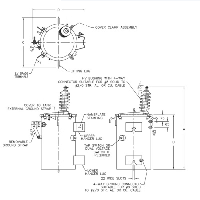
6KV/10KV/13.8KV/15kV/ 10KVA/15KVA/25KVA/37.5KVA/50KVA/100KVA Pole Mounted Single Phase Circle Tank Shape Transformer
| Capacity | H.V | L.V | Connection | No-load loss (W) | On-load loss (W) | Impedance |
|---|---|---|---|---|---|---|
| 5 | 6 6.3 10 10.5 11 |
0.22~0.24 | li0 li6 |
24 | 130 | 3.5 |
| 10 | 36 | 235 | ||||
| 16 | 44 | 330 | ||||
| 20 | 52 | 385 | ||||
| 30 | 64 | 560 | ||||
| 40 | 80 | 700 | ||||
| 50 | 96 | 855 | ||||
| 63 | 116 | 1020 | ||||
| 80 | 128 | 1260 | ||||
| 100 | 152 | 1485 | ||||
| 125 | 184 | 1755 | ||||
| 160 | 232 | 2130 |
FAQ
1.What is a pole-mounted transformer? What are the differences between it, a box-type substation, and an indoor transformer?
①Installation Method: Pole-mounted transformers are installed overhead without occupying land; box-type substations and indoor transformers are installed on the ground and require land resources.
②Cost: Pole-mounted transformers have the lowest cost, with no need for civil construction; box-type substations and indoor transformers require foundations and boxes/workshops, resulting in higher costs.
③Capacity and Application: Pole-mounted transformers have a smaller capacity (usually ≤500kVA) and are suitable for distributed loads; box-type substations and indoor transformers can have a larger capacity and are suitable for areas with more concentrated loads and aesthetic or safety requirements (such as residential communities and shopping malls).
④Maintenance: Maintenance of pole-mounted transformers requires pole climbing or the use of aerial work vehicles; box-type substations and indoor transformers can be maintained on the ground, which is more convenient and safe.
2.What are the environmental requirements for installing a pole-mounted transformer?
①Altitude: Usually not exceeding 1000 meters. Special design (enhanced insulation) is required for high altitudes.
②Ambient Temperature: -25℃ ~ +40℃ (depending on specific models and specifications.
③Installation Location: Should avoid flammable, explosive, heavily polluted and extremely low-lying areas prone to waterlogging. The utility pole foundation should be solid.
④Distance from Surrounding Objects: Must comply with safety regulations, such as maintaining a sufficient distance from buildings, trees, roads, etc.
3.Is it normal for a pole-mounted transformer to make a "buzzing" sound during operation? Under what circumstances is the sound abnormal?
①Sudden increase in sound and heavy tone: May be due to overload operation.
②Uneven “cracking” or “discharging” sound: Internal insulation breakdown or local discharge exists, which is very dangerous. The transformer must be shut down immediately for inspection.
③Loud, uneven noise accompanied by vibration: May be due to loose bolts or screws of the internal iron core or clamping parts.
4.How to determine if a transformer is overloaded? What are the hazards of overload operation?
①Accelerated Insulation Aging: For every 6-8℃ increase in temperature, the insulation life is halved.
②Fault Induction: Long-term overload may cause insulation damage, resulting in serious faults such as inter-turn short circuits and phase-to-phase short circuits.
③Shortened Service Life: Long-term operation at high temperatures significantly shortens the transformer’s service life.
④Current Measurement: Use a clamp ammeter to measure the low-voltage side outgoing current and compare it with the transformer’s rated current.
⑤Temperature Monitoring: Abnormal increase in oil temperature or shell temperature is an obvious sign of overload (intelligent transformers can directly read data).
5.What is the function of transformer oil? Under what circumstances does it need to be replaced or refilled?
①Low Oil Level: Observe through the oil level gauge. If the oil level is below the lower limit scale, check for leaks and add new oil of the same model.
②Oil Deterioration: Take an oil sample for testing. If the electrical strength (breakdown voltage) is unqualified, the acid value is too high, or the dielectric loss factor (tanδ) exceeds the standard, the oil needs to be filtered or replaced with new oil.
③Functions: Insulation, heat dissipation, and arc extinguishing in circuit breakers.
6.What causes the high-voltage fuse to blow? How to handle it?
①Safe Operation: Open the low-voltage switch and use an insulating rod to remove the blown fuse tube.
②Preliminary Inspection: Observe the transformer for abnormal appearance (oil spraying, bulging, burning smell).
③Insulation Measurement: Use a megohmmeter to measure the insulation resistance of the transformer’s high-voltage side, low-voltage side to the ground, and between windings.
④Analysis and Judgment: If the insulation resistance is seriously unqualified, there is a high possibility of an internal fault, and the transformer needs to be returned to the factory for maintenance. If the insulation is normal, a new fuse of the same specification can be replaced and a test power transmission can be performed once. If the fuse blows again, a thorough inspection of the line and transformer must be conducted.
7. What should be noted for pole-mounted transformers during the thunderstorm season?
①Inspect Lightning Protection Devices: Ensure that the zinc oxide lightning arrester is firmly installed, the grounding down conductor is reliably connected, and the grounding resistance is qualified (usually required to be ≤4Ω or 10Ω). This is the most important preventive measure.
②Clean the Surrounding Environment: Trim the branches of nearby trees to prevent short circuits or discharges caused by branches overlapping the lines during thunderstorms and strong winds.
③Strengthen Inspections: After thunderstorms, special inspections of transformers and lines should be conducted to check for insulator flashover, lightning arrester operation (damage), fuse blowing, and other phenomena.
Why Choose us ?
Built to last, engineered to perform.
Kete Transformer is a key national-level manufacturer specializing in transformers, recognized as a “Contract-Honoring and Promise-Keeping” enterprise, a high-tech enterprise, and a national-level enterprise technology center. It is recommended in the national directory for rural and urban power grid construction and renovation, as well as a recommended supplier of major electromechanical equipment for hydropower projects. Its products have been awarded the title of “National Quality Inspection Qualified Product – Quality Trustworthy Product” and “Nationally Recognized Product for Mechanical Industry Users.
Our Project
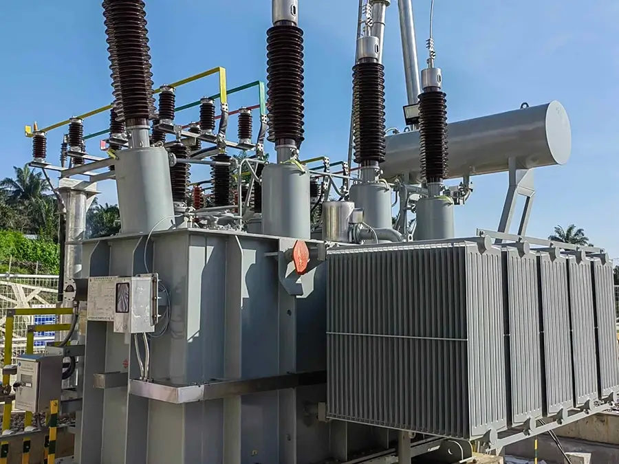
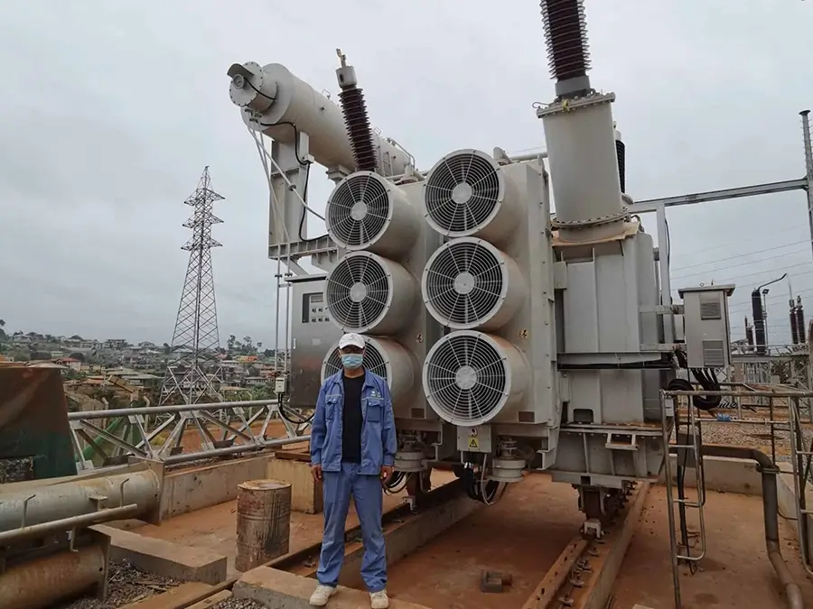
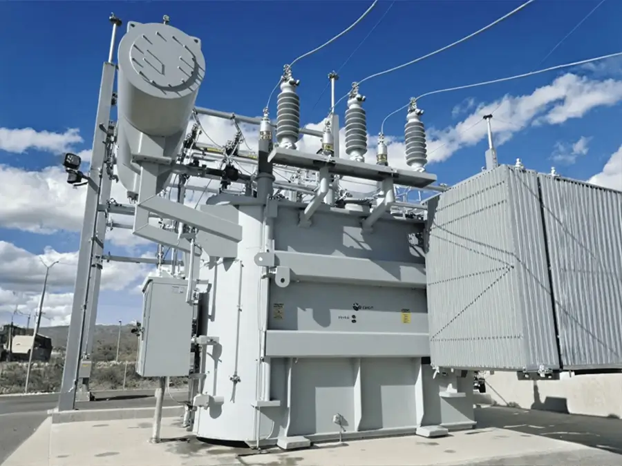
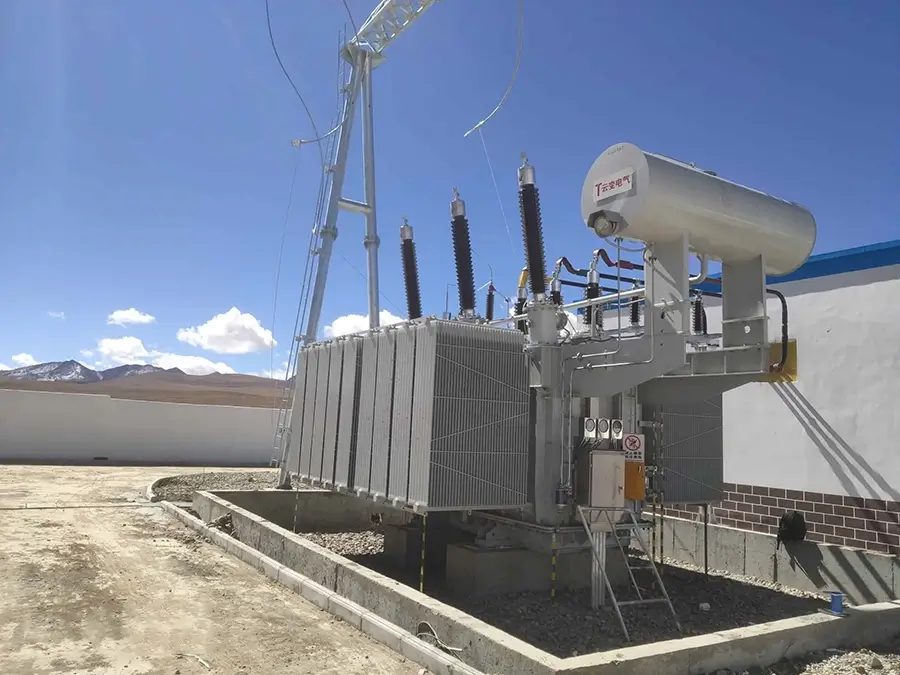
Our products not only dominate the domestic market but are also exported to more than 30 countries and regions, including Russia, Southeast Asia, Africa, and the Americas, serving industries such as power, municipal engineering, metallurgy, and petrochemicals.